

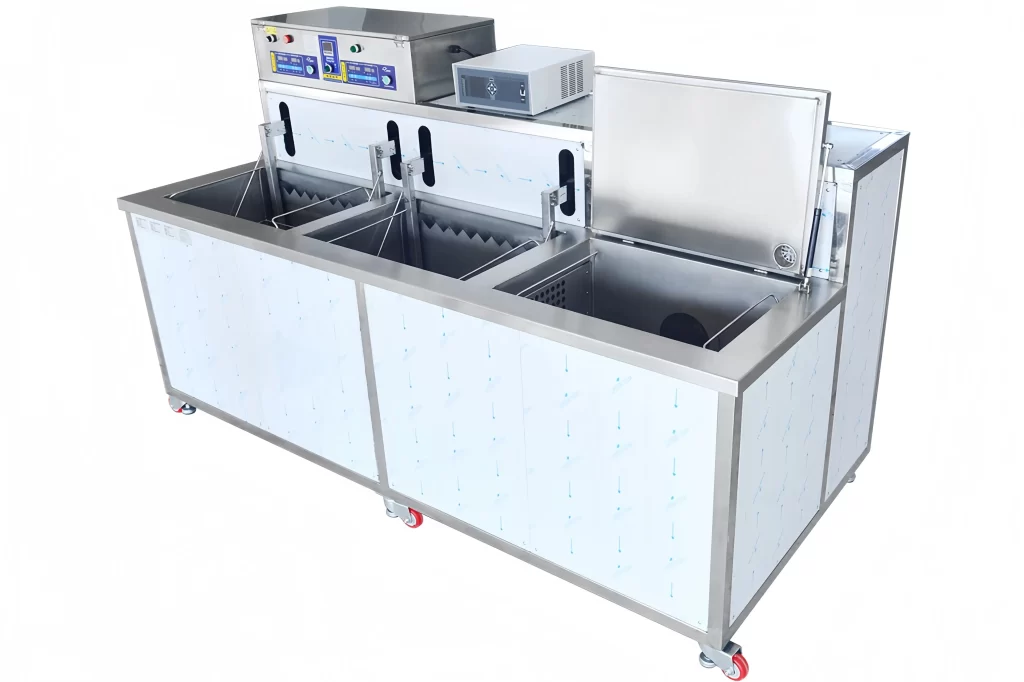
When specifying automated cleaning for high-volume production, the gap between a system that works on paper and one that runs consistently across three shifts is where throughput targets die. Tunnel ultrasonic cleaning systems are not simply long tanks with transducers; they are engineered continuous-flow machines where conveyor geometry, ultrasonic power density, and drying architecture directly determine whether your line moves at the speed you need. After two decades designing and deploying these systems across automotive, fastener, and consumer electronics factories, I've found that the decisions with the biggest throughput impact are often the ones addressed last in a spec discussion.
Tunnel Ultrasonic System Capabilities for High-Throughput Production
A tunnel ultrasonic cleaning system integrates multiple processing stages — washing, ultrasonic degreasing, rinsing, drying — into a single inline machine. Parts enter on a conveyor, pass through each station, and exit clean and dry, without manual handling. The core advantage is not simply automation; it is that cleaning becomes a deterministic process rather than a batch-dependent one.
The throughput of a tunnel system depends on conveyor speed multiplied by part density per unit length of belt. But speed cannot be dialled up arbitrarily. If ultrasonic exposure time falls below the minimum required to cavitate contaminants loose, cleanliness fails. The system must balance conveyor velocity against the effective length of the ultrasonic tank and the cleaning chemistry's action time. In practice, a well-designed tunnel system for high-throughput applications runs conveyors at speeds between 0.5 and 1.5 metres per minute for small to medium parts, with tank lengths of 2 to 5 metres providing sufficient dwell time.
Design Factors That Determine Cleaning Throughput and Quality
The throughput you get from a tunnel ultrasonic cleaning system is not a single published number. It emerges from the interaction of several physical parameters. I'll walk through the ones that have caused the most redesigns in projects I've been involved with.
Ultrasonic power density matters first. Most industrial systems run at 10–20 watts per litre, but for high-throughput applications with heavy oils or tenacious cutting fluids, 25–30 W/L keeps cavitation intensity up when conveyor speed increases. Frequency choice follows the contaminant type. We use 20–25 kHz for bulk degreasing of steel stampings, 40 kHz for parts with fine threads or blind holes, and 80 kHz for polished aluminium where surface damage is unacceptable. Multi-frequency staging, with lower frequencies in first tanks and higher frequencies in rinse tanks, often delivers the best balance.
Tank length and dwell time form the throughput equation. Conveyor speed (m/min) × tank length (m) determines ultrasonic exposure. For a typical stamping degreasing application, we target 90–120 seconds of ultrasonic contact. A 3-metre tank at 1.5 m/min yields 2 minutes exactly, which aligns well with aqueous detergent action at 55–65 °C. If you shorten the tank without adjusting chemistry or temperature, you will leave residues that show up later in coating or assembly. I've seen factories try to compensate by raising cleaning temperature beyond the detergent's effective range, which only degrades the chemistry faster and increases evaporation losses.
Conveyor and Basket Engineering for Continuous Part Flow
Conveyor design inside a tunnel ultrasonic system determines how parts are presented to the cleaning zones. A flat wire mesh belt is adequate for parts that rest stably on one face, but it cannot handle components that nest or trap liquid. Roller conveyors work for palletised heavy parts like engine blocks but reduce the ultrasonic exposure per cycle because the rollers block sound transmission.
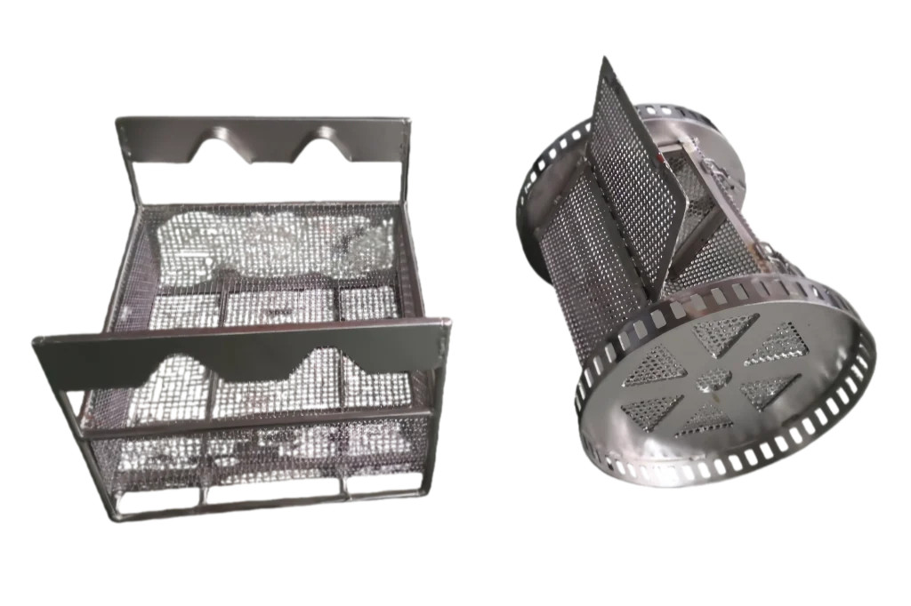
For high mix, high volume applications, we often recommend custom baskets travelling on a chain conveyor. Baskets orient parts so that blind holes and internal cavities drain. They also allow different part families to run on the same line without manual changeover, provided the basket pockets are designed with sufficient clearance. The basket material must withstand the cleaning chemistry and temperature. Stainless steel 304 is standard; 316 handles mild acids and DI water rinses. For weight-critical applications like aluminium castings, a stainless frame with PTFE contact points prevents galvanic marking.
Aqueous Versus Solvent Tunnel Systems: Matching Media to Production Requirements
The choice of cleaning medium — water-based detergent or solvent — fundamentally shapes the tunnel system's throughput and infrastructure needs. Aqueous systems use heated detergent solutions and require multiple rinse stages with deionised water to prevent spotting, plus substantial drying capacity. A complete aqueous tunnel for stamping parts might run six to eight linear metres and demand a DI water plant on site. The payback is low per-part chemical cost and broad material compatibility.
Solvent-based tunnel systems, typically using hydrocarbon or modified alcohol under vacuum, collapse cleaning, rinsing, and drying into a shorter footprint. A single-station hydrocarbon ultrasonic vacuum system can degrease, vapour-rinse, and vacuum-dry in 8–12 minutes total. This makes them attractive where factory floor space is tight or where DI water supply is not feasible. The trade-off is higher initial capital, solvent management, and the need for integrated recovery distillation. In a factory running 20,000 parts per day, solvent losses of even 200 litres per month add up, so we size the distillation loop to handle peak throughput conditions, not average.
Integrating Tunnel Cleaners into Automated Production Lines
A tunnel ultrasonic cleaning system is rarely a standalone island. Typically it receives parts from a machining cell or stamping press and delivers them to an assembly station or packaging line. Integration means more than physical conveyor linking. The control system must communicate upstream and downstream through PLC handshaking to pause the cleaning line if the next process stops, or to accelerate within safe limits if buffers are full.
The conveyor entry zone also requires design attention. Parts arriving from a vibratory feed or robotic pick-and-place can pile up if the loading point changes speed suddenly. We typically install a short accumulation conveyor before the wash zone with sensors that meter parts into the tunnel at a constant rate. For high-throughput fastener lines, our GTKCLEAN conveyor tunnels run at 0.8 to 1.0 m/min and feed up to 2 tonnes of parts per hour through oil-water separation, cleaning, rinsing, and drying. The oil separator pulls more than 98% of surface oil from the wash solution, keeping the wash bath clean for a full shift without dumping.
Operational Cost Drivers and Long-Term System Reliability
Throughput discussions quickly turn to capital cost, but the costs that determine whether a tunnel ultrasonic system earns its place on the floor are operational. The largest ongoing expense is often cleaning chemistry: detergent replenishment, DI water consumption, and waste disposal. Filtration and oil separation reduce these, but they must be sized for the maximum contaminant load, not the average. A spray pre-wash at the tunnel entry removes loose chips and heavy oils before ultrasonic cleaning starts, extending bath life two- to threefold.
Energy cost splits between heating and ultrasonic generation. Insulated tanks, heat recovery on dryer exhaust, and ultrasonic generators with power modulation (ramping power back when no parts are in the tank) cut thermal losses. A well-insulated tunnel system running at 60 °C typically consumes 40–65 kWh in actual operation, even if installed power ratings are higher. This is a figure we validate during commissioning because it directly affects the customer's monthly utility bill.
Maintenance reliability in tunnel systems centres on the conveyor drive, transducer health, and filtration pump uptime. We prefer direct-drive motors with variable frequency control and stainless steel chains that tolerate detergent exposure without lubrication. Transducer monitoring circuitry can detect individual element degradation before it causes a cleaning failure, and should be specified in the initial scope. These features add upfront cost but pay back within months in a line producing 24/7.
If your program requires throughput above a few hundred kilograms per hour or demands multi-step cleaning with tight consistency targets, I recommend reviewing the full set of design parameters with your equipment partner before finalising any layout. An engineer who has commissioned tunnel systems in production environments can spot the mismatches between a drawing and what actually happens when parts start moving. For questions specific to your parts and production volume, reach out to me at [email protected] or call +86 17768507147 — send your target throughput and part material, and I'll help you confirm the configuration before it gets locked into a purchase order.
Common Questions From Production Teams About Tunnel Ultrasonic Cleaning
How fast can a tunnel ultrasonic system clean parts?
Conveyor speed typically ranges from 0.5 to 1.5 m/min for mass production, translating to hundreds of kilograms per hour depending on part size. Throughput is not about moving the conveyor faster; it is about matching tank length, ultrasonic power, and chemistry to deliver the required dwell time. For a 3-metre ultrasonic tank, 90 seconds of exposure at 1.2 m/min is realistic for most stamping and machining oil removal.
Does a tunnel system require an on-site DI water plant?
In most aqueous tunnel designs, multiple rinse stages need deionised water to prevent spotting, so a DI plant is standard. Solvent-based tunnel systems use vacuum drying and do not need water rinsing, which eliminates the DI water requirement entirely. The choice hinges on whether your facility can support water treatment infrastructure and whether your parts tolerate solvent contact.
Can a single tunnel washer handle multiple part shapes?
Yes, if the basket design accommodates variation and the conveyor loading position is consistent. We often design modular basket inserts that nest different geometries while keeping cavities open for drainage. Without this, parts with deep blind holes may carry detergent into the rinse stages, causing cross-contamination that drags down subsequent cleaning cycles.
What is the most common cause of throughput loss after installation?
Inadequate filtration of the wash tank. When oil and particulate build up faster than the filtration loop removes them, ultrasonic cavitation weakens and cleaning time must increase, slowing the conveyor. A well-sized oil-water separator combined with 50-micron bag filtration and regular skimming typically prevents this. We recommend auditing the filtration system's throughput capacity at peak load, not average conditions.
Is solvent cleaning faster than aqueous?
Solvent systems often have shorter overall cycle times because drying is near-instantaneous under vacuum. A hydrocarbon vacuum tunnel can complete a full wash-rinse-dry cycle in 8–12 minutes for batches, compared to 15–20 minutes for an aqueous line with hot-air drying. However, solvent systems carry higher chemical cost and require solvent recovery infrastructure, so the throughput advantage must be weighed against total cost of ownership for your specific part volume. If you're evaluating both, share your production targets and we'll compare the lifecycle numbers — contact us at [email protected].
Если вас интересует, ознакомьтесь с этими связанными статьями:
Системы ультразвуковой мойки в линию для повышения контроля процесса
Выбор подходящей ультразвуковой системы для вашего производства
 Russian
  English
  German
  Spanish
  French
  Portuguese