
When a hydraulic valve body tests within particle limits after machining but fails audit after assembly, the first place I look is not the production process—it is the cleaning data. Contaminants that are invisible at the component level redistribute during operation, and the cleanliness code on the component specification becomes irrelevant if cleaning isn't designed against the correct standard. This article explains how ISO cleanliness standards apply to hydraulic components and why verification requires looking at particle counts, measurement protocols and the cleaning method itself rather than any single published number.
Which Standards Govern Hydraulic Component Cleanliness
ISO cleanliness standards form a structured system. Three documents cover most component-level requirements: ISO 4406 defines the cleanliness code format itself, assigning range numbers to particle counts per millilitre of fluid at three size thresholds (≥4 µm, ≥6 µm, ≥14 µm). ISO 16232 applies to road vehicle fluid circuits and specifies extraction methods for components—agitation, pressure rinsing, ultrasonic extraction—and the reporting of results as either particle counts or ISO 4406 codes. ISO 18413 addresses hydraulic power component cleanliness, providing procedures for inspecting and reporting residual contamination after manufacturing.
The standard that often gets less attention during equipment selection is ISO 21018, which specifies continuous particle monitoring instruments and their calibration requirements. We have seen production lines where the cleaning machine is validated under ISO 16232 but the inline particle monitor is not verified to ISO 21018, creating a blind spot no amount of ultrasonic power will fix.
A common misunderstanding I encounter is treating ISO 4406 codes as product specifications. A code like 18/16/13 is a measurement result expressed in a standardised format, not a cleanliness requirement written into the hydraulic component's engineering specification. That requirement typically comes from the OEM or system integrator and references a specific ISO test method. If the equipment specification says "particle count per ISO 16232, agitation method," running an ultrasonic extraction because it yields better numbers invalidates the result.
How Particle Counts Are Measured and Why the Method Changes the Number
The measurement protocol—not just the equipment—determines the final cleanliness code. ISO 16232 recognises several extraction techniques, and they produce meaningfully different results from the same component.
Agitation extraction suspends the part in clean test fluid and applies mechanical movement. Pressure rinsing forces fluid through internal passages at controlled pressure. Ultrasonic extraction uses cavitation energy to dislodge particles adhered to surfaces. We have validated all three methods across different component geometries, and the ultrasonic extraction almost always recovers more particles from internal cavities and blind holes. The number it generates is higher, but it is also more complete.
The correct method is the one specified in the component drawing, the quality plan, or the customer agreement. Running a more aggressive extraction method and reporting that result as the component cleanliness value may look defensible, but it changes the acceptance baseline and can flag conforming parts as nonconforming.
Inline particle monitoring during production cleaning introduces a second layer of complexity. These instruments—typically light-extinction or light-scattering optical particle counters—report real-time contamination levels. Their readings correlate with laboratory extraction results only when the extraction method, monitor calibration standard, and particle size thresholds are explicitly aligned. If the inline monitor reports ISO 4406 codes from a different size threshold set than the final extraction test uses, the two values will not match, and chasing the difference wastes production time.
How Contaminant Type, Size and Location Affect the Cleaning Approach
Cleanliness codes aggregate all particles above a size threshold into a single range number, but hydraulic components care about particle identity. Hard particles—silicon carbide from grinding, aluminium oxide from blasting, steel chips from machining—produce abrasive wear at clearances measured in single-digit microns. Soft contaminants like fibres or residual stamping lubricant clog control orifices rather than abrading surfaces, but they cause different failure modes at different particle counts.
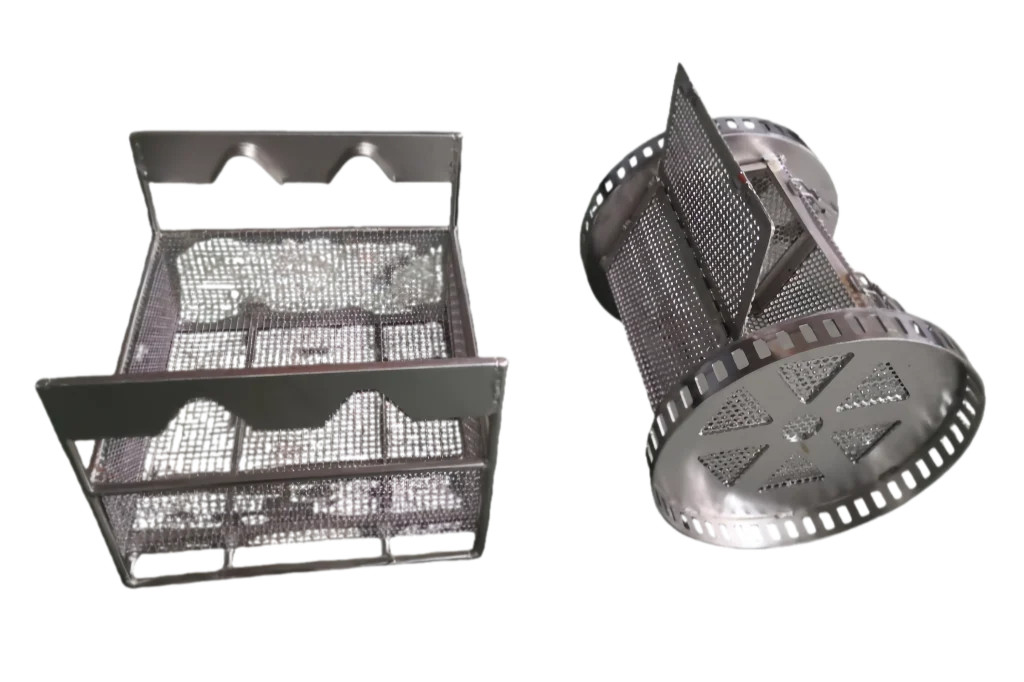
Component geometry determines where particles accumulate and whether a cleaning system can reach them. Blind threaded holes in a manifold block, intersecting cross-drilled passages in a spool valve body, and small-bore pilot lines all trap contaminants. A multi-tank ultrasonic system that couples cleaning, rinsing and drying in sequence solves some of these problems for complex parts because the cavitation penetrates internal volumes that spray impingement does not reach. We have configured rotary basket systems for hydraulic manifolds specifically because the 360-degree rotation exposes trapped air pockets and allows entrapped particles to evacuate rather than settle back after each cleaning stage.
Particle size distribution is at least as important as the total count. A component that meets its >14 µm specification but carries elevated 4–6 µm counts will still cause erosion in high-speed proportional valves over time. I have seen hydraulic pump housings with excellent post-cleaning ISO 4406 results fail long-term durability tests because the residual fine particle load slowly abraded the port plate surface. The cleaning target should specify size thresholds that match the component's operational clearances, not a generic code.
Aligning Cleaning Equipment with ISO Verification Requirements
The cleaning system design determines whether the process can consistently hit a cleanliness target, and the target determines how the cleaning system should be configured.
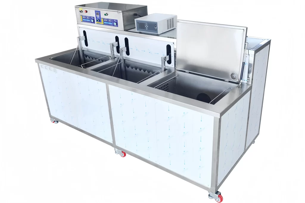
Multi-stage ultrasonic systems pair rough ultrasonic degreasing, fine ultrasonic cleaning, multiple rinse stages and drying in one automated sequence. For hydraulic components requiring 18/16/13 or tighter codes, we build systems with DI water rinsing at ≤30 µS/cm conductivity to leave no dissolved solids on part surfaces, circulatation filtration on every tank to keep the cleaning fluid itself clean throughout the production day, air knife or vacuum drying to prevent water spotting that becomes a particle on the final extraction test, and automated basket transfer that eliminates operator handling contamination after the clean stages.
Single-tank manual systems can work for components with relaxed cleanliness requirements or for maintenance cleaning, but they introduce operator variability. The final rinse quality in a manual system depends on an operator's diligence—not a PLC program—and proving process capability for tight ISO codes becomes harder with each manual step added to the sequence.
Continuous inline tunnel systems for fasteners, connectors and small hydraulic fittings address a different problem: throughput. The ISO cleanliness requirement is the same whether the part is cleaned one at a time or ten thousand per hour, but the capital equipment and process validation approach are entirely different. A tunnel system running at the required throughput rate with sufficient rinse stages feeding a common water treatment system is designed around the production volume, not just the cleanliness code.
If your hydraulic assembly line runs mixed part numbers each calling for different particle limits, a critical equipment decision is whether the cleaning system can store programs with parameters matched to each part number's verification protocol—tank temperatures, ultrasonics power levels, rinse dwell times, drying selection—or whether the operator must manually adjust them between batches.
Matching Cleaning Chemistry to Contaminant
The cleaning chemistry selection follows directly from what the ISO extraction is going to measure. Water-based alkaline detergents remove water-soluble coolants and light machining oils but leave behind residues that a subsequent DI rinse stage must clear. Hydrocarbon solvents dissolve heavy preservative greases and stamping compounds more effectively and dry faster because they evaporate at lower temperatures, but the solvent itself becomes part of the cleanliness chain. A recovered solvent with elevated particulate levels recontaminates parts in the cleaning tank, raising the particle count on the extraction test.
We have run comparison trials using the same hydraulic manifold design cleaned with aqueous detergent versus hydrocarbon solvent, then extracted per ISO 16232 ultrasonic method. The solvent system produced lower particle counts on the first cleaning cycle, but the aqueous system with proper DI rinse and filtration held more consistent results across a production shift because the solvent's own contamination load increased with throughput.
Practical Steps for Verifying Cleanliness in Production
A cleanliness verification program that holds up under audit requires tighter control than periodic random sampling. What I recommend based on production-line diagnostic work:
First, establish the baseline using the agreed extraction method from the component specification. If the specification only states an ISO 4406 code without specifying the extraction method, stop and request clarification. A 18/16/13 code from agitation extraction means a different residual contamination level than the same code from ultrasonic extraction, and no amount of cleaning adjustment will reconcile them if the method itself is unstated.
Second, calibrate the inline particle monitor to the extraction method used for final verification. We align monitor threshold settings to the same particle size channels the extraction test reports. The correlation between monitor reading and extraction result needs to be established with a minimum of 30 production parts run through both tests, not assumed from manufacturer specifications.
Third, the cleaning fluid's own particle load creates a false ceiling on achievable cleanliness. Running the system with circulation filtration continuously operating reduces this, but the filters must be maintained. A saturated 10 µm filter turns into a particle generator that steadily raises the baseline contamination level of the cleaning medium.
Fourth, drying matters. Air knife drying leaves residual moisture in internal cavities of complex hydraulic components. That moisture evaporates and leaves behind dissolved solids that show up as particles in the extraction test. For components with target codes of 15/13/10 or tighter, vacuum drying removes this variable entirely because the water evaporates at low temperature with no air impingement.
Fifth, the extraction fluid blank value must be measured and subtracted. ISO 16232 requires reporting a blank value for the extraction fluid itself. If the blank concentration is more than 10% of the component cleanliness value, the results become unreliable and the test fluid lot should be investigated before rejecting production parts.
Common Questions About ISO Cleanliness and Hydraulic Parts
Do tighter cleanliness codes always require more expensive cleaning equipment?
Not necessarily in a linear way. What changes more directly is the verification cost and the process control effort. Moving from 20/18/15 to 18/16/13 requires the same fundamental cleaning technologies—ultrasonic degreasing, rinsing, drying—but demands tighter rinse water quality, cleaner starting fluid, and more frequent extraction testing. The equipment cost increases primarily when production throughput must be maintained at the higher cleanliness level. A manual single-tank system may technically achieve 18/16/13 for one part, but producing one thousand parts per day at that code reliably will require automated multi-stage equipment and a validated water treatment system.
How often should cleanliness extraction tests be run in production?
The frequency depends on the component's risk level and the process stability. Hydraulic components going into flight-critical aircraft systems typically undergo 100% verification or very high-frequency sampling. Industrial hydraulic components with a demonstrated stable process may sample every 50–100 parts or once per shift, depending on the quality agreement. What matters is that the sampling frequency is written into the quality plan, not adjusted in response to a single out-of-spec result without investigating the root cause.
Can one cleaning system handle hydraulic components with different cleanliness targets?
Yes, but the system must store part-specific programs—ultrasonic power, tank temperatures, rinse stages, drying selection, process timing—and the operator must trigger the correct program for each part number. Without program storage, the operator must manually set parameters between batches, which introduces variability that the verification test will detect. We have designed multi-tank systems for contract manufacturers who run twenty or more hydraulic part numbers through the same machine by building programs matched to each customer's ISO specification and extraction protocol.
When different cleanliness codes coexist on the same production line, the cleaning fluid contamination level across all tanks must be maintained at the tightest specification's requirement, and the rinse water quality must meet the same standard. Compromising on shared resources for the easier parts puts the tighter-spec parts at risk.
If your hydraulic component cleanliness program needs cleaning equipment that integrates with the ISO verification protocol you are working to, send your part drawings, target code and throughput requirement to [email protected] or call +86 17768507147. We will evaluate the cleaning configuration, process steps and supporting water or solvent treatment system specific to your parts and confirm the achievable cleanliness range with sample testing before you commit to equipment specifications.
If you're interested, check out these related articles:
Multi-Tank Ultrasonic Cleaning: A Deep Dive into Industrial Configurations
Automated Cleaning Equipment: A Beginner’s Industrial Guide
Why Coating Manufacturers Choose GTKCLEAN Pre-Coating Cleaning Equipment
 English
  German
  Spanish
  French
  Russian
  Portuguese