Ultrasonic Cleaning and Regeneration System for SCR
In the production processes of industries such as power, iron and steel, cement, transportation, and metallurgy, flue gases containing nitrogen oxides (NOₓ) are generated. Nitrogen oxides (NOₓ) cause severe environmental pollution, therefore, enterprises‘s implementation of flue gas denitrification plays a positive role in environmental protection and enhancing their social responsibility.
Selective Catalytic Reduction (SCR) is defined as a process that uses a catalyst to enhance the rate of chemical reactions between nitrogen oxides (NO x) and ammonia, resulting in the production of nitrogen and water.This technology has developed rapidly in recent years and been widely applied in Western Europe and Japan.
The key principle of the SCR denitrification reactor is that under the action of a catalyst, by injecting a reducing detergent, the reducing detergent fully mixes with the high-temperature flue gas (300-400°C) and selectively reacts with NOₓ in the flue gas to generate environmentally harmless nitrogen (N₂) and water (H₂O).
After more than 30,000 hours of operation, the denitrification efficiency and activity of SCR decrease significantly. The surface of aged catalysts is obviously blocked, leading to a reduction in specific surface area, a decrease in micropores and total pore volume, and the disappearance of micropores, thereby affecting catalyst performance.
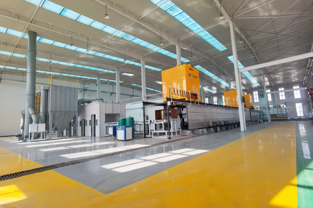
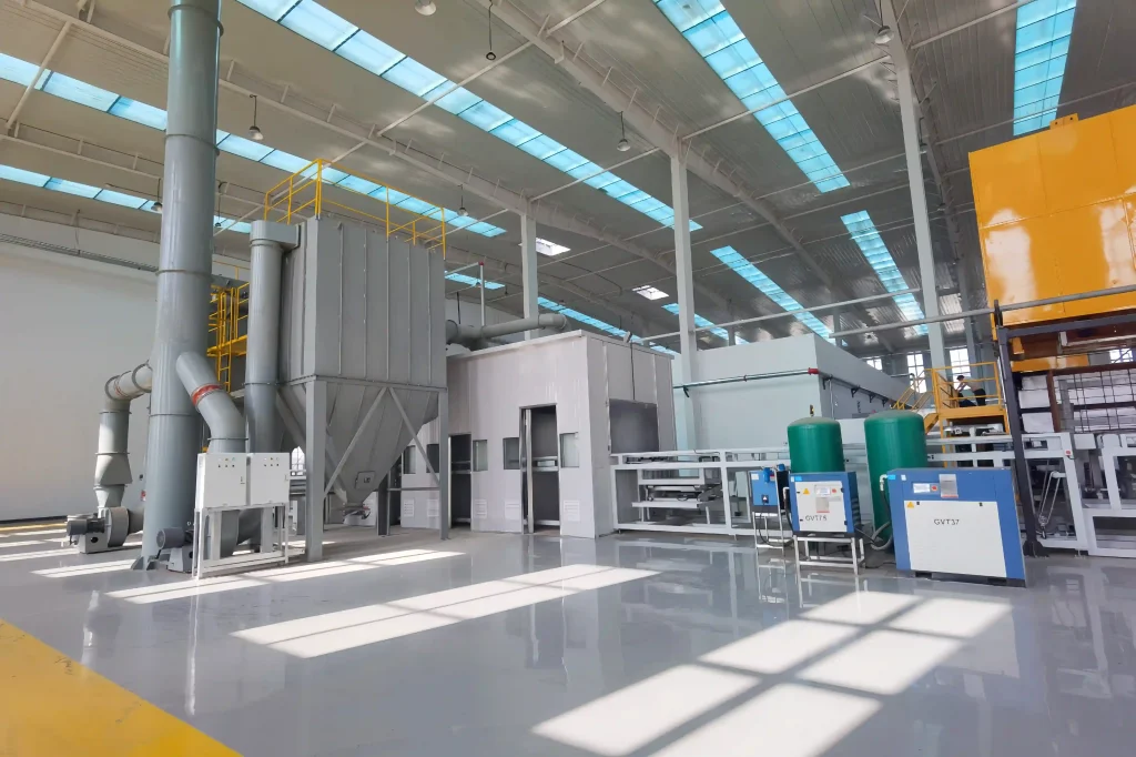
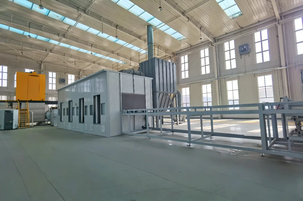
SCR catalyst ultrasonic cleaning and regeneration system restores the activity of denitration catalysts through advanced technologies. In operation: First, the ultrasonic cleaning tank uses high-frequency vibration to precisely break down micron-scale adherent impurities in the catalyst pores.The catalyst is then transferred to an automated calcination furnace for “energy activation” to recover its catalytic activity.A reciprocating agitation assembly addresses material caking issues during the process.
Post-regeneration, the catalyst achieves:
- Catalytic activity recovery exceeding 98% of new catalysts
- Ammonia slip less than 3 ppm
- Conversion rate of sulfur dioxide (SO₂) and sulfur trioxide (SO₃) less than 1%
- Mechanical properties remaining essentially consistent with pre-regeneration levels
Key Focuses of Equipment Design and Manufacturing
- GTK’s R&D team has secured 11 patents for the catalyst cleaning and regeneration system, providing proprietary technical support for the whole system.
- Having supplied equipment to over 50 clients, our engineers possess extensive experience in cleaning catalyst modules under complex working conditions and with high sludge loads.
- Fully automated operation is realized at all stations with no manual intervention, except for manual forklift loading and unloading.
- A rational high-efficiency soot blowing process is specially designed to remove surface dust from catalysts, complemented by an integrated dust collection system.
- The ultrasonic technology engineered by GTK delivers concentrated energy to the inner pores of catalysts, ensuring ultrasonic waves penetrate deeper into the cavity structure.
- Combined with high-power ultrasonic output, it significantly enhances the cleaning efficacy.
- Compatibility-oriented design: The automated system is compatible with catalysts of dimensions 1850–2000 mm (L) × 910–1000 mm (W) × 700–1700 mm (H).
Process Flow Table
| No. | Process Equipment Name | Working Medium | Operating Temperature (℃) | Quantity | Unit | Supporting Chemical Preparation Tank/Equipment |
| a | Forklift Loading Station | / | RT | 1 | Station | Buffers for 3 module stations |
| b | Automatic Scanning Air Knife | High-Pressure Air | RT | 1 | Station | Automatic scanning by manipulator |
| c | Manual Inspection Station | / | / | 1 | Station | / |
| d | Automatic Scanning Air Knife | High-Pressure Air | RT | 1 | Station | / |
| e | Manual Inspection Station | / | / | 1 | Station | / |
| f | Conveyor Turning Station | / | / | 1 | Station | / |
| 0 | Automatic Loading Station | / | / | 2 | Piece | Automatically docks with physical ash blowing and unloading, detects module size and automatically centers |
| 1 | Ultrasonic Cleaning | Reclaimed Water | RT-45℃ | 1 | Unit | / |
| 2 | Automatic Spray Cleaning | Reclaimed Water | RT | 1 | Unit | / |
| 3 | Ultrasonic Cleaning | Tap Water | RT-45℃ | 1 | Unit | / |
| 4 | Bubbling Chemical Cleaning Tank | Chemicals prepared with Tap Water | RT-45℃ | 1 | Unit | 1 piece (Volume > 4 m³) |
| 5 | Bubbling Rinsing Tank | Pure Water | RT-45℃ | 1 | Unit | / |
| 6 | Bubbling Chemical Cleaning Tank | Pure Water | RT-45℃ | 1 | Unit | 1 piece (Volume > 4 m³) |
| 7 | Ultrasonic Rinsing Tank | / | RT-45℃ | – | – | / |
| 8 | Bubbling Rinsing Tank | / | RT-45℃ | – | – | / |
| 9 | Drying Oven | Electrically Heated Air | 150℃ | 1 | Unit | Constant temperature for 2 hours |
| 10 | Active Loading Tank A | Active Chemicals | 50-60℃ | 1 | Unit | 1. 1 stock solution preparation tank (4 m³); 2. 2 make-up solution preparation tanks (2.5 m³ each) |
| 11 | Active Loading Tank B | Active Chemicals | 50-60℃ | 1 | Unit | / |
| 12 | Automatic Unloading Station | / | / | 1 | Set | With water draining and collection function |
| 13 | High-Temperature Calcination | Hot Air | 450℃ (Adjustable) | 10 | Station | / |
| 14 | Forklift Unloading Station | / | RT |
Equipment Parameters
| Item | Data |
| Overall Dimensions | 61000mm × 32000mm × 7200mm (L×W×H) |
| Electric Power | ≤1500KW, adopting energy-saving design |
| Compatible Product Dimensions | 1850-2000mm (Length) × 910-1000mm (Width) × 700-1700mm (Height) |
| Design Cycle Time | 40-60 minutes/piece (adjustable) |
| Control System | Mitsubishi brand touch screen and PLC, with automatic control operation (including remote software upgrade service) |
If you need more detailed requirements, please feel free to contact us.