Most production engineers understand that ultrasonic cleaning consumes less energy than thermal or high-pressure spray methods, yet when I review equipment specs with procurement teams, the conversation rarely moves past the ultrasonic generator wattage. What gets missed is that energy consumption in an industrial ultrasonic system is a multi-variable equation — heating power, pump sizing, drying technology, and even basket design all contribute. The standards that define how these systems are measured and compared are not obscure; they are just underutilized during equipment evaluation. If you are specifying a cleaning line today and your supplier cannot show you a complete energy profile backed by recognized measurement protocols, you are building a recurring cost into your operation that could have been designed out.
How Energy Efficiency Is Defined for Industrial Ultrasonic Cleaning Equipment
Most of the industrial ultrasonic cleaning equipment on the market does not carry a standalone energy-efficiency label like a household appliance. Instead, energy performance is assessed through a combination of component-level electrical standards, system-level thermal and fluid efficiency metrics, and process-specific benchmarks. The defining documents for our own system design work come from three directions. IEC 60034-30-1 covers the motor efficiency classes for pumps, conveyors, and automated basket transfer mechanisms — when a supplier tells you a conveyor drive is "high efficiency," this standard tells you which IE class it actually meets. For the ultrasonic generator itself, we reference GB/T 19843 (equivalent to ISO 20816 for mechanical vibration) alongside manufacturer efficiency curves; a generator running at 28 kHz or 40 kHz may show 85–92% conversion efficiency from electrical input to acoustic output, but this drops outside its designed impedance band. Heating elements, which often account for the largest continuous load in a multi-tank system, should be specified to IEC 60335-2-73 for industrial liquid heaters, and our team typically sizes them with a 10–15% margin above the theoretical heat loss calculation rather than over-specifying by 30% or more, which remains a common field issue.
These component standards provide the baseline. What they do not capture is the interaction between subsystems. A pump motor that meets IE4 on the test bench may run at partial load for 80% of the cycle in a real cleaning line because the filtration circuit was sized for a worst-case particulate load that only occurs in one shift. The pump efficiency rating then becomes irrelevant; what matters is the actual annual energy consumption at the operating point. This is where system-level analysis becomes necessary, and why component-level specifications alone can be misleading.
Where Energy Standards Meet Real Production Conditions
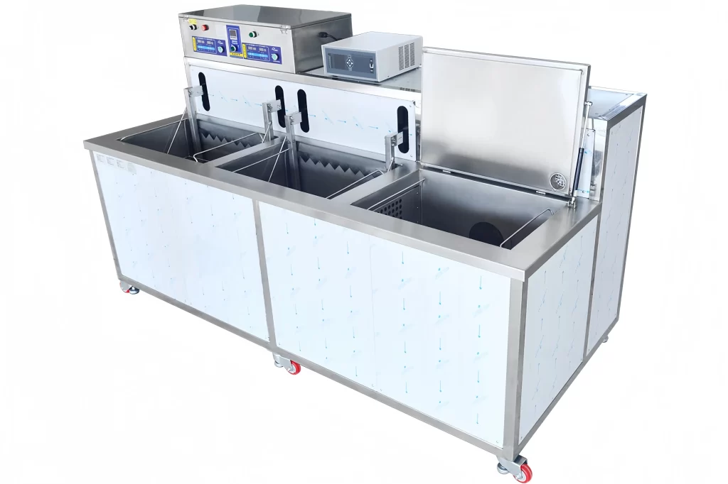
In our experience deploying automated cleaning lines across more than 20 countries, the gap between design-efficiency calculations and measured site consumption almost always traces back to auxiliary systems, not the ultrasonic transducers. The heated rinse tanks, recirculation pumps, and drying modules collectively outweigh the generator's load in most multi-stage configurations. For a typical four-tank aqueous system running at 55°C with hot-air drying, we have measured the following distribution across multiple installations:
| Subsystem | Share of Total Energy Consumption |
|---|---|
| Tank heating (cleaning + rinse stages) | 40–55% |
| Hot-air drying module | 20–30% |
| Ultrasonic generators | 12–18% |
| Pumps, conveyors, controls | 8–15% |
These proportions shift with chemistry. A hydrocarbon solvent system with vacuum drying eliminates the large heated rinse tanks but adds a distillation recovery circuit that runs continuously during production. We recently configured a multi-tank hydrocarbon line where the distillation heater and vacuum pump together consumed more energy than the ultrasonic cleaning tanks. The standard that matters in that case is not an ultrasonic standard — it is the heat recovery efficiency of the distillation column and whether the vacuum pump is staged to reduce its duty cycle between batches.
What this means practically is that specifying energy targets at the machine level without understanding the process duty cycle produces misleading comparisons. Two systems with identical ultrasonic generator ratings can have annual energy costs that differ by 40% or more, driven entirely by tank insulation quality, pump sizing discipline, and drying technology selection. When we audit an existing cleaning line for energy performance, we start with the production log — hours per shift, batches per hour, parts mass per batch — and work backward to calculate the actual thermal load, not the nameplate heater rating.
Practical Rules for Evaluating Energy Performance in a Cleaning System Specification
Evaluating energy efficiency in a cleaning system proposal requires going beyond the generator specifications and asking the right thermal and mechanical questions. Drawing from our work with procurement engineers, I recommend four hard requirements to include in your RFQ or technical specification.
First, require the supplier to provide a calculated energy balance for the entire machine at your production rate, not just a list of installed power ratings. The balance should show heat input from heating elements, heat loss through tank walls, heat carried out by the parts and baskets, and heat recovery from any recirculation or exhaust systems. We generate these as a standard engineering deliverable during the design phase; the calculation identifies oversized heaters, undersized insulation, or missing heat recovery opportunities before the machine is built.
Second, ask specifically about the partial-load efficiency of pumps and motors. Many multi-stage lines run filtration pumps continuously even during basket transfer steps when no cleaning is happening. A pump specified at the best efficiency point will waste energy if it operates for 60% of the cycle at 30% of rated flow. Variable-frequency drives on pumps and conveyor motors are a straightforward solution, but they need to be specified in the controls architecture — retrofitting them adds cost and complexity that early specification avoids.
Third, evaluate the drying module separately. Air-knife systems, hot-air convection, and vacuum drying each carry different energy profiles and different achievable dryness levels. In applications where a trace of moisture is acceptable — many in-process cleaning steps — we recommend air-knife drying, which consumes roughly 60% less energy than hot-air drying. Where we need bone-dry surfaces for coating or assembly, vacuum drying is the most energy-intensive option but eliminates the long dwell times that hot-air ovens require. The trade-off is between capital cost and operating cost, and it should be calculated with your actual parts geometry, because thin-walled aluminum parts dry faster and need less aggressive drying than thick steel components.
Fourth, treat tank insulation as a hard specification, not an afterthought. We have seen installations where a 500-liter tank at 60°C lost over 3 kW continuously because the supplier used 25mm rock wool instead of the 50mm mineral wool we specify as standard. Over a year of two-shift operation, that single specification difference costs the operator roughly $2,500 in electricity, and the incremental insulation cost is under $300. It is one of the highest-return energy decisions in the entire system.
Minimizing Energy Costs Through Process Design and Technology Selection
Process architecture does more to determine energy consumption than any individual component specification. A poorly designed cleaning process will consume electricity at a high rate regardless of how efficient the ultrasonic generator is.
On the process side, the single largest energy optimization we recommend is splitting the heated rinse stage into a warm first rinse and a hot final rinse rather than heating both tanks to the same temperature. The first rinse removes the bulk of the detergent carryover; it only needs to be warm enough to prevent thermal shock and maintain solubility. The final rinse temperature determines drying effectiveness. In a four-tank system, dropping the first rinse from 60°C to 40°C cuts that tank's heating load by roughly one-third, with no measurable impact on final cleanliness when the final rinse and drying parameters are held constant. Over 5,000 operating hours, this change alone can save 15,000–25,000 kWh, depending on tank volume and production throughput.
The second underused strategy is heat recovery from the dryer exhaust. Hot-air dryers discharge warm, humid air continuously, and unless the factory make-up air system is carefully balanced, that heat is lost. A closed-loop dryer with an integrated condensing section recovers roughly 60% of the energy from the exhaust air and recirculates it. The capital cost adder is modest when specified at the design stage — it requires a heat exchanger and condensate management — but retrofitting a dryer in the field to recover heat is expensive and disruptive. For solvent systems with vacuum drying, the recovered solvent carries latent heat that a well-designed distillation circuit can recirculate to preheat incoming solvent, reducing the distillation heater's duty cycle.
Third, the choice between batch and continuous conveyance affects energy intensity per part. A conveyorized system with consistent throughput runs all subsystems at steady state; heating elements cycle on and off within a narrow band, pumps run at constant speed, and the drying module does not experience cold-start thermal cycles between batches. A batch system that starts and stops multiple times per shift incurs a heat-up penalty each time the tanks come back to temperature after an idle period, and this penalty compounds with poorly insulated tanks. For production volumes above roughly 200 kg of parts per hour on a two-shift schedule, we typically see the energy-per-part crossover point where continuous inline cleaning becomes more efficient than batch processing, even accounting for the higher conveyor power draw.
Getting Purchase Approval by Framing Energy Costs as CapEx vs. OpEx
Engineering managers who understand the energy profile of a cleaning system still need to justify the equipment investment to finance. Framing the discussion around standards helps. When we support customers building a capital appropriation request, we structure the energy analysis as a comparison between a base-case system with standard components and a high-efficiency configuration with the optimization measures I have described. The energy consumption difference is converted to annual operating cost using the customer's actual electricity rate, and this operating cost is compared to the incremental capital cost.
In a typical 4-tank aqueous system processing 500 kg of steel parts per hour on one shift, the high-efficiency configuration adds roughly 8–12% to the equipment price — primarily from VFDs, upgraded insulation, and an air-knife drying system where hot-air was used in the base case. The annual energy savings, at $0.12/kWh, run between $8,000 and $14,000 depending on local climate and production hours. This yields a simple payback of 18–30 months on the incremental investment, and the payback improves with higher electricity rates or multi-shift operation.
If your accounting team requires a formal standard to reference, ISO 50001 (Energy Management Systems) provides the framework for establishing an energy baseline, measuring improvement, and documenting the performance indicators — though the actual machine-level calculations will come from your supplier's engineering data. I recommend asking for energy performance data that follows the measurement boundaries defined in ISO 14955-1 for machine tools, as the principles translate well to cleaning equipment even though the standard was written for machining centers.
Common Questions About Industrial Ultrasonic System Energy Use
How much does it cost to run an industrial ultrasonic cleaner per hour?
A mid-sized aqueous ultrasonic cleaning system with one 600W generator, a 200L heated tank at 55°C, a rinse tank, and hot-air drying typically draws between 8 and 25 kW depending on whether all stages are active. At $0.12/kWh, that translates to $0.96–$3.00 per hour. The range is wide because the drying module and tank heaters dominate; a system running with an air knife instead of hot air will sit at the lower end, while a system with vacuum drying and multiple heated rinse tanks will approach the upper end. The most accurate figure comes from your supplier's energy balance calculation at your production rate rather than a generic estimate.
Do higher ultrasonic frequencies use more energy?
Not directly. A 40 kHz generator does not inherently consume more power than a 28 kHz generator at the same wattage rating. The efficiency of electromechanical conversion depends on the impedance match between the generator and transducer, not the frequency itself. Where we see energy differences is in the cleaning application: higher frequencies produce smaller cavitation bubbles and gentler cleaning, which can require longer cycle times or higher chemical concentrations to achieve the same soil removal. If cycle time extends from 5 minutes to 8 minutes because of the frequency choice, the heating and pumping systems run longer per batch, increasing total energy per part. The generator energy is secondary to the process time extension in that scenario.
Can I retrofit an older ultrasonic system to reduce its energy consumption?
Retrofitting is usually cost-effective for tank insulation upgrades, adding VFDs to pump motors, and replacing resistive heating elements with more efficient designs. It becomes less attractive for dryer conversions — switching from hot-air to air-knife drying often requires different part handling and fixturing, which means modifying the conveyor or basket system. For systems more than 15 years old, we generally recommend a full energy audit before committing to partial upgrades, because the cumulative efficiency gap between the old system and a new design frequently justifies replacement on a 3–5 year total cost of ownership basis rather than incremental retrofit.
What is the most overlooked factor that drives up energy costs in ultrasonic cleaning?
Tank liquid management. When rinse tanks are not equipped with conductivity-controlled overflow, operators tend to set a continuous overflow rate that is higher than necessary to maintain water quality. A 200L rinse tank overflowing at 2 L/min continuously discards heated water that the system already paid to warm, and the make-up water must be heated from ambient temperature. Installing a conductivity sensor that triggers overflow only when dissolved solids exceed the setpoint typically reduces rinse water consumption by 30–40% and eliminates a significant fraction of the heating load that no one budgets for. If you are reviewing energy costs and the rinse system lacks conductivity control, that is the first place to look.
To evaluate where energy standards apply to your specific cleaning application, our engineering team can provide a system-level energy balance during the specification phase. Send your part dimensions, production throughput, and cleanliness requirements to [email protected] or call +86 17768507147, and we will confirm the energy profile and identify which optimization measures deliver the fastest payback for your production line.
If you're interested, check out these related articles:
Semi-Automated Ultrasonic Cleaning for Medium-Volume Production
Selecting Industrial Parts Washers for CNC Machining Success
Automated Ultrasonic Cleaning Systems for Advanced Manufacturing
Budgeting for Industrial Cleaning Equipment Upgrades A Strategic Guide