
You can prove the cleaning on paper and still get contaminated parts at the end of the shift. When an inline ultrasonic system is integrated into a smart factory line, the failure is rarely the cleaning itself — it is that the machine ran within specification while the line upstream changed something without telling it. In more than twenty years of designing automated cleaning systems for production environments, I have seen this pattern repeat across automotive, aerospace, and electronics lines. The parts arrive slightly different — a new coolant, a faster cycle, a different die release — and the cleaning system, tuned to last month's conditions, keeps running exactly as programmed. Parts come out looking clean. Coating adhesion tells a different story weeks later. This article covers what changes when ultrasonic cleaning moves from a standalone cell into an inline configuration inside a smart factory — particularly how part transfer speed, real-time feedback loops, and cleaning chemistry decisions interact in ways that a specification sheet alone will not reveal.
What Separates Inline Ultrasonic Cleaning from Batch Systems
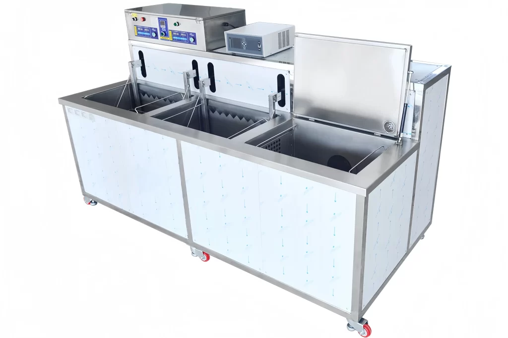
An inline ultrasonic cleaning system sits inside the production flow. Parts arrive on a conveyor or transfer mechanism, pass through cleaning, rinsing, and drying stages, and exit directly into the next manufacturing operation — coating, assembly, or inspection. No operator moves baskets between tanks. No accumulation of dirty parts waiting for a batch cycle to finish. The system runs at the pace of the line feeding it.
That integration changes the design requirements in three ways that batch systems do not face. First, cleaning cycle time is locked to the production takt time. If the upstream CNC cell delivers a part every 45 seconds, the cleaning system has 45 seconds per part — not a flexible window. Second, part orientation matters continuously rather than at loading only. In a batch rotary system, the basket rotation can compensate for poor initial orientation. Inline, the part travels through fixed spray and ultrasonic zones and the orientation it enters with is the orientation it keeps. Third, drying must complete within the allocated conveyor length. There is no holding station where a wet part can wait for residual moisture to evaporate — the part reaches the end of the line and must be dry and ready for the next process.
Underneath these mechanical constraints is a cleaning physics problem. Ultrasonic cavitation in an inline tank works differently than in a batch immersion tank because the part is moving through the ultrasonic field rather than sitting stationary within it. The exposure time per surface is shorter and the cavitation intensity must be calculated for a moving target. In practice this means the transducer placement, frequency selection, and power density have narrower tolerances in an inline configuration. A batch system with 28 kHz transducers covering the tank floor works because the part soaks in the field for five minutes. The same cleaning result inline at 45 seconds per part requires higher power density or multi-frequency coverage — typically 28 kHz and 40 kHz alternating — and the transducers must be positioned to match the part trajectory, not just the tank volume.
How Smart Factory Connectivity Changes Cleaning System Behavior
The term "smart factory" gets used loosely. For inline ultrasonic cleaning, the distinction that matters is whether the cleaning system receives data from upstream processes or merely reports its own status to a SCADA interface. Most cleaning equipment suppliers offer the second. The difference between the two is the difference between catching a contamination problem at the cleaning station and catching it at the coating adhesion test three days later.
A cleaning system that reads upstream data can adjust before parts enter the tank. If the CNC coolant concentration shifts — something that happens gradually as water evaporates and operators top up — the cleaning chemistry may need a corresponding adjustment in detergent concentration or rinse flow rate. A standalone system has no way to know the coolant changed until cleaning quality drifts. An inline system integrated into the factory network can receive that data point and either alert an operator or, in a closed-loop configuration, adjust its own dosing accordingly.
Temperature is another variable that benefits from upstream data. Parts arriving from a machining operation carry heat. If the machining coolant is running at 35 °C and the parts move directly into the cleaning line, the ultrasonic tank temperature profile changes from what was modeled during commissioning. A smart system compensates by modulating heating or cooling. A dumb system runs at its setpoint and the cleaning result shifts without explanation.
The practical value of connectivity shows up most clearly during product changeovers. In a batch cleaning cell, changeover means swapping baskets and possibly changing a program. In an inline smart factory configuration, the cleaning system can receive the next part number from the MES, load the corresponding cleaning recipe — tank temperatures, ultrasonic power levels, conveyor speed, detergent dosing — and confirm readiness before the first new part arrives. This reduces the window where parts run with the wrong parameters from minutes to seconds. For lines producing multiple part variants on the same conveyor, that window is the difference between zero rejected parts and an entire shift of questionable cleanliness.
Conveyor Speed, Part Geometry, and the Ultrasonic Exposure Equation
The most common mistake I see in inline ultrasonic cleaning specifications is treating conveyor speed and ultrasonic cleaning as independent decisions. A production engineer sets the line speed based on throughput targets. A cleaning engineer specifies the ultrasonic system based on soil type and cleanliness requirements. When those two decisions meet on the factory floor, the part moves faster than the cavitation can clean it.
The relationship is straightforward but unforgiving. Ultrasonic cleaning requires a minimum exposure time — the duration a given surface spends inside the active cavitation zone. That minimum depends on the contaminant: light cutting oil may need 30 seconds of effective cavitation; drawing compound or heat treatment scale may need 90 seconds or more. The conveyor speed determines how long the part stays inside the ultrasonic tank. If the tank length is two meters and the conveyor runs at one meter per minute, exposure time is two minutes. If the same tank runs at three meters per minute, exposure drops to 40 seconds.
The fix is not always a longer tank. Tank length adds floor space and chemistry volume, both of which increase cost. An alternative is higher ultrasonic power density, which reduces the minimum exposure time by increasing cavitation intensity per unit of time. In our work with CNC aluminum shell inline cleaners, we have found that running 28 kHz transducers at approximately 2 W per liter in a batch configuration can be pushed to 3 to 4 W per liter in an inline configuration to achieve equivalent cleaning at shorter dwell times. The trade-off is that higher power density can damage delicate surfaces and increases the risk of cavitation erosion on softer materials. Aluminum and brass parts require careful power mapping — the transducer layout must deliver high intensity where the soil is and lower intensity where the substrate is vulnerable.
Part geometry adds a second layer. A flat stamping passes through the ultrasonic field with all surfaces equally exposed. A machined housing with blind holes travels through the same field, but the cavitation must reach inside those holes to clean them. Conveyor speed that works for the external surfaces may be too fast for the internal ones. The solution is frequently a combination of ultrasonic and targeted spray — the ultrasonic handles general cleaning and the spray nozzles direct cleaning solution into the blind features. But this requires the spray manifold to be positioned precisely relative to the part as it moves, which is an alignment and fixturing challenge that batch systems do not face.
| Parameter | Batch Rotary | Inline Conveyor | Inline Considerations |
|---|---|---|---|
| Typical cycle time per part | 5–8 minutes | 30–90 seconds | Locked to takt time; tank length and power must compensate |
| Ultrasonic power density | 1.5–2.5 W/L | 2.5–4 W/L | Higher intensity for shorter dwell; material limits apply |
| Part orientation flexibility | Basket rotation | Fixed per fixturing | Orientation at loading determines cleaning coverage |
| Changeover time | 5–15 minutes | Under 60 seconds | MES integration eliminates manual recipe switching |
| Drying completion | Extended dwell possible | Must complete within conveyor length | Air knife plus hot air or vacuum; no wet-part buffer |
Cleaning Chemistry in an Inline System: What Changes and Why
Solvent and aqueous cleaning both work in inline configurations, but the chemistry management changes in ways that are easy to underestimate during specification. In a batch system, the cleaning solution sits in a tank and is filtered and recirculated. Contamination builds gradually, and bath life is measured in weeks or months. An inline system exposes the cleaning solution to parts continuously — every part that passes through deposits some amount of soil into the chemistry. The contaminant load rises faster, and the bath life calculation shifts.
This affects solvent selection. Modified alcohol solvents and hydrocarbon solvents both work inline, but their behavior under continuous loading differs. Hydrocarbon solvents with a distillation recovery system can maintain consistent cleanliness longer because the solvent is continuously purified. The distillation unit removes the oil and returns clean solvent to the tank. Modified alcohols rely more on filtration and periodic replacement — effective for lighter soils but requiring closer monitoring in high-throughput inline applications. For smart factory integration, inline monitoring of solvent purity via refractive index or density sensors closes the loop: the system detects when purity drops below a threshold and either triggers distillation or alerts for solvent replacement. Without that monitoring, the solvent degrades silently and cleaning quality fades.
Aqueous chemistries face a different challenge. The detergent concentration must stay within a narrow band. Too little and cleaning fails. Too much and parts carry residue into the rinse stages, which then requires more rinse water to remove. In a batch system, operators can test concentration once per shift. In an inline system running continuously, a concentration drop between tests means potentially hundreds of parts cleaned inadequately. Automated conductivity-based dosing systems solve this — they measure the cleaning solution conductivity, compare it to the target, and dose detergent as needed. This is not a luxury feature for smart factory inline cleaning. It is the only way to maintain consistent cleaning quality across a full production shift.
Rinse water quality is the silent variable. An inline system that runs DI water rinses needs the DI water system to keep up with continuous demand. If the DI water resistivity drops from 18 MΩ·cm to 10 MΩ·cm, parts exit the rinse stage with ionic contamination that will cause coating failures or corrosion. A smart factory configuration monitors rinse water resistivity in real time and can divert parts or pause the line if the water quality drifts out of specification. The cost of that monitoring is small compared to the cost of shipping contaminated parts to a customer.
Designing the Drying Stage for Zero Carryover
Drying is where inline systems face their hardest test. A batch system can extend the drying cycle if parts are not dry. An inline system cannot — the part reaches the conveyor end at a fixed time regardless of whether it is dry. If the drying stage is undersized relative to the conveyor speed and part complexity, wet parts enter the next process.
The physics are simple. Drying removes liquid from part surfaces. Air knives blow bulk water off. Hot air evaporates residual moisture. Vacuum drying pulls moisture out of blind holes and internal cavities by lowering the boiling point. The conveyor speed determines how long each drying method has to work. If the conveyor runs at two meters per minute and the drying tunnel is three meters long, drying time is 90 seconds. If that is not enough, the options are longer tunnel, slower conveyor, or more aggressive drying — higher air velocity, higher temperature, or vacuum assist.
Part complexity drives the drying method selection. A simple stamping dries adequately with air knife and hot air. A machined housing with blind holes holds water that air knives cannot reach. For those parts, vacuum drying or extended hot air with part rotation — difficult to achieve inline — becomes necessary. The alternative that we have used in fastener tunnel cleaners and similar high-volume applications is a multi-zone drying section: high-velocity air knife to strip bulk water, followed by hot air impingement at 80 to 120 °C for evaporation, followed by a cooling zone so parts are handleable at exit. The zones are sized independently so the most difficult part feature determines the drying length, not the easiest.
One detail that gets overlooked in specification: carryover of rinse water into the drying zone. If parts exit the final rinse dripping wet, the drying system works harder than designed. A well-designed inline system places a drip zone or air knife immediately after the final rinse to strip excess water before the part enters the main drying section. That small addition can cut drying energy consumption by 20 to 30 percent because less water enters the hot air zone. In a system running 24 hours a day, that difference compounds.
Real-Time Monitoring and What It Should Actually Track
Smart factory integration creates an expectation that everything is measured. For inline ultrasonic cleaning, measuring everything is possible but measuring the right things is what separates a useful system from a data-generating distraction. The variables that actually predict cleaning quality are fewer than most SCADA screens suggest.
Ultrasonic power output, measured at the transducer or generator, tells you the system is running but not whether cavitation is effective. Cavitation intensity varies with temperature, dissolved gas content, and contamination loading — all of which change during a production shift. A better metric is the cleaning result itself, but inline cleanliness measurement is difficult. The practical compromise that works in production is monitoring the inputs that control the output: detergent concentration, rinse water conductivity, solvent purity, bath temperature, and conveyor speed. If those five variables stay within their validated ranges, cleaning quality stays consistent. If any one drifts, quality drifts with it — and the system should alert before parts leave the line.
Bath contamination monitoring deserves special attention. In a hydrocarbon solvent inline system, the distillation unit automatically maintains purity, but the distillation rate must match the contamination input rate. If the line speeds up and more oil enters the solvent per hour, the distillation system may fall behind. Monitoring the solvent level in the clean tank provides an indirect but reliable indicator: if the level drops, either solvent is being carried out on parts faster than it is being recovered, or the distillation rate is insufficient. Both conditions need attention before they affect production.
For aqueous systems, filtration is the equivalent of distillation. Multi-stage filtration — bag filters for coarse particles, cartridge filters for fine particles, and sometimes activated carbon for organic contaminants — extends bath life, but the filters load up. Monitoring pressure drop across the filter stages gives a direct indication of when filters need replacement. Ignoring it means eventually the filters bypass and contamination circulates back to the cleaning tank. By then, parts have already been cleaned inadequately and the problem is downstream.
When an Inline System Is the Right Choice — and When It Is Not
Inline ultrasonic cleaning makes sense when the production volume and line integration justify the engineering investment. The threshold is not absolute — it depends on part variety, cleanliness requirements, and what happens to the parts after cleaning. But some patterns are consistent across the projects I have worked on.
Inline is the right choice when parts move directly from machining or forming into a coating or assembly operation with no buffer inventory between them. The cleaning system must keep pace, and inline is the only configuration that does. Volume alone does not dictate the decision. A line producing 500,000 parts per month benefits from inline. A line producing 5,000 parts per month of highly variable geometry may be better served by a multi-tank batch system with manual or semi-automated transfer — the changeover flexibility of batch outweighs the speed of inline when part variety is high.
Inline is also the right choice when cleaning consistency across high volumes matters more than the ability to handle part variety. A fastener tunnel cleaner running one part number for a full shift achieves cleaning consistency that a batch system handling mixed loads cannot match. Every part sees the same spray pattern, the same ultrasonic exposure, the same drying profile. In a batch system, parts in the center of the basket may clean differently than parts at the edges. Inline removes that variable — at the cost of flexibility.
The wrong application for inline is a line with frequent part changes, low individual part volumes, or cleaning requirements that differ significantly between parts. Converting a batch system to inline for those conditions adds conveyor complexity and changeover time without improving cleaning quality. In those cases, a well-designed multi-tank ultrasonic system with programmable recipes and semi-automated basket transfer delivers better overall economics. The decision comes down to whether the production line itself is continuous. Inline cleaning follows the line configuration — it does not create it.
For smart factory applications, the question is slightly different. Even if the volume justifies inline mechanically, does the data integration provide enough additional value to justify the automation engineering? If the upstream processes are stable and the cleaning chemistry is forgiving — light oil removal with aqueous detergent, for example — the data feedback loop may not change outcomes. If the upstream processes are variable and the cleanliness requirement is tight — pre-PVD coating cleaning of optical or medical components — the data integration becomes not just valuable but necessary. No amount of offline quality inspection catches contamination introduced between inspection and coating. The inline monitoring catches it before parts leave the cleaning line, and that is the difference between a contained problem and a recall.
Common Questions About Inline Ultrasonic Cleaning for Smart Factories
Does an inline ultrasonic system require a dedicated operator?
Not in steady-state production. Once the system is commissioned and recipes are validated, an inline ultrasonic cleaning system integrated into a smart factory should run with no more than periodic monitoring. The PLC manages tank temperatures, conveyor speed, detergent dosing, and fault detection. Operators intervene for replenishment, filter changes, and unplanned stops — typically a few minutes per hour rather than continuous attendance. The labor saving relative to a manual batch system is frequently the single largest line item in the ROI calculation.
Can an inline system handle multiple part types on the same conveyor?
Yes, but the conveyor speed, fixture design, and recipe switching must all support it. Mixed-part production works when the parts share similar geometry and cleaning requirements so the same conveyor speed and ultrasonic settings produce acceptable results for all variants. When cleaning requirements differ — one part needs 60 seconds of ultrasonic exposure, another needs 90 — the conveyor speed cannot satisfy both simultaneously without a recipe change. Recipe switching triggered by part-in-place sensors or MES integration resolves this, but adds control complexity. The alternative is to design the line so the conveyor speed accommodates the most demanding part and faster-cleaning parts simply get extra exposure, which costs throughput but avoids complexity.
How does inline ultrasonic cleaning compare to vapor degreasing for high-volume production?
Inline ultrasonic with aqueous or hydrocarbon chemistry and vapor degreasing are different technologies targeting different cleanliness levels and throughputs. Vapor degreasing with modified alcohol or chlorinated solvents achieves extremely low residue levels and is well suited to precision components. Inline ultrasonic handles higher throughput and integrates more easily with aqueous chemistries where solvent use is restricted. For smart factory applications where parts move continuously from machining to assembly, inline ultrasonic with aqueous chemistry and real-time monitoring is the more common choice. Vapor degreasing typically runs as a batch or indexed inline process — parts enter a sealed chamber, cycle through vapor and immersion stages, and exit. The chamber sealing requirement limits the continuous throughput relative to an open conveyor inline ultrasonic configuration.
What is the most common cause of cleaning failure in an inline system after commissioning?
Contamination loading exceeding the design basis. The system is commissioned with a specific soil type and volume in mind — say, 10 grams of cutting oil per part, 500 parts per hour. Six months later, the upstream process changes: a new coolant, a faster machining cycle that leaves more chips, or a different forming lubricant. The cleaning system has not changed, but the soil load has, and the chemistry, filtration, or ultrasonic exposure that worked at commissioning no longer produces the same result. The fix starts with identifying what changed upstream, but the better approach is building the monitoring that detects the change automatically — solvent purity, detergent concentration, filter pressure drop — so that the system alerts before parts are compromised. For specific contamination profiles or if your line is handling parts with deep blind features, share your part drawings and current cleaning challenge at [email protected] or call +86 17768507147 — the right monitoring setup depends on what the parts look like and what is on them.
If you're interested, check out these related articles:
Automated Cleaning Equipment: A Beginner’s Industrial Guide
Automated Ultrasonic Cleaning: Elevating Industrial Process Consistency
The Engineer’s Guide to Pre-Coating Surface Preparation
Parts Washer Selection: A Manufacturer’s Definitive Guide
 English
  German
  Spanish
  French
  Russian
  Portuguese