
When a machined component fails quality inspection because of a few particles lodged inside a 0.5‑mm cross‑hole, the problem is rarely the cleaning chemistry alone. It is typically a failure to design the cleaning process around the specific geometry and contaminant profile of the part — a disconnect I have seen repeatedly while supporting automated cleaning lines in over 20 countries. Meeting precision manufacturing cleanliness standards depends first on translating a target specification into concrete equipment and process decisions, from ultrasonic frequency selection to basket rotation and drying method. Without that translation, even an expensive, certified cleaning system will produce inconsistent results.
Cleanliness standards define quality in precision manufacturing
In precision manufacturing, a cleanliness standard is a contract between a part and the next process. A hydraulic valve body destined for an aerospace assembly line does not simply need to “look clean”; it must meet a specified particle count limit, typically expressed as an ISO 16232 cleanliness level or a maximum non‑volatile residue (NVR) per unit area. The consequences of missing that target range from coating adhesion failures to catastrophic field failures.
ISO 14644‑1 classifies cleanroom environments by airborne particle concentration, but that is not a parts cleanliness standard — a distinction that often gets blurred. The actual cleanliness of a manufactured component is measured by extracting contaminants from the surface and quantifying them through gravimetric analysis, optical particle counting, or scanning electron microscopy. Each method reveals a different slice of the truth: a part that passes gravimetric limits may still fail when individual particle size distribution is considered, especially in fuel systems or optical assemblies where even a single 50‑µm particle is a reject.
The specification an engineer chooses must match the failure mode it prevents. For example, in medical device manufacturing, residual detergent left on a part is as critical as particulate contamination because it interferes with biocompatibility. In PVD coating applications, surface cleanliness is measured not just by particle count but by surface energy, verified through water break or dyne testing. If the standard is selected without understanding the downstream process, the measured value becomes irrelevant.
Measuring cleanliness combines particle count, NVR, and surface inspection
There is no single instrument that gives a complete cleanliness reading. A combination approach is standard practice in high‑reliability manufacturing. Particle counting (either by optical microscopy or automated scanners) quantifies the size distribution of solid debris. NVR analysis, conducted by rinsing the part with a solvent and evaporating the eluent, captures dissolved or thin‑film contaminants that a particle counter will miss. For surface‑sensitive parts, a water break test or contact angle measurement reveals whether residue is changing how coatings or adhesives will bond.
The difficulty we encounter in our cleaning line designs is not the measurement technique itself but the interaction between part geometry and extraction method. A blind threaded hole may trap 60% of the total particulate load, yet a simple spray extraction for NVR can miss it entirely if the solvent does not fully displace the trapped air. I have seen cases where a part passed cleanliness certification after a bench‑top extraction, only to fail immediately when a customer performed a more aggressive cavitating extraction on the same lot. The standard only works if the extraction procedure is matched to the geometry. That is why cleanliness specifications in precision manufacturing are increasingly defining not just the limit but the extraction protocol — typically referencing ISO 18413 for hydraulic components or internal company standards derived from it.
Ultrasonic cleaning technology achieves sub‑micron contaminant removal
For contaminants trapped in narrow recesses, ultrasonic cavitation remains the most effective method for achieving the particle counts that aerospace, medical, and optical manufacturers demand. The mechanism is physical: microscopic bubbles implode against the part surface, generating local pressure spikes that dislodge particles even from blind holes and internal intersections. The cleaning result, however, depends on selecting the right frequency — a choice not all equipment buyers consider early enough.
Lower frequencies around 20‑28 kHz produce violent cavitation and excel at removing large chips and heavy oils from machined components. As we move into the 40‑80 kHz range, the cavitation becomes gentler and the bubbles are smaller, allowing them to penetrate into micron‑sized gaps without damaging delicate substrates. For a CNC‑machined aluminum housing that will be PVD coated, a 40 kHz multi‑tank line with a final ultrapure water rinse and hot air drying is often the difference between a consistent dyne level across the entire surface and a coating that flakes off weeks later.
The other variable that often gets black‑boxed is the cleaning chemistry. The ultrasonic energy is the delivery mechanism; the cleaning fluid does the work. In solvent‑based systems, hydrocarbon solvents heated to 40–60°C cut stamping oils effectively, and when combined with vacuum ultrasonic and vacuum drying, they reach the interior of parts that would otherwise retain liquid. Aqueous systems, which use alkaline or neutral detergents and DI water, are the preferred route when the next process is coating or assembly that cannot tolerate solvent residue. The choice between these approaches should be driven by the residue specification, not by a generic equipment label.
Automated cleaning line design determines achievable cleanliness levels
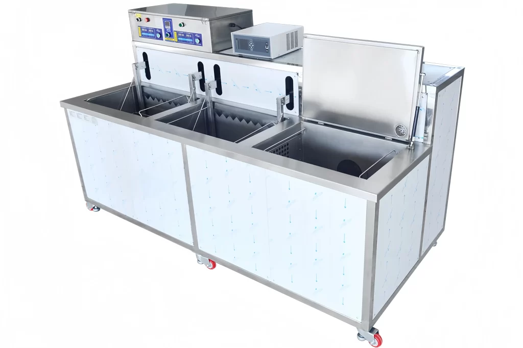
If the cleanliness target is, for example, a maximum particle size of 50 µm with zero visible residue, the cleaning line must be engineered backwards from that outcome. Single‑tank ultrasonic systems can clean many industrial parts to a commercial standard, but for precision manufacturing, multi‑tank configurations with separate wash, rinse, and drying stations are closer to a requirement than an option. Each tank isolates a fluid condition: the first wash tank removes bulk contamination, a second ultrasonic rinse or cascading overflow tank displaces the dirty fluid, and a pure DI water rinse brings conductivity down to the level required — our systems typically reach ≤0.06 µS/cm for pre‑coating lines to prevent water spots and secondary contamination.
Drying is where many lines lose the cleanliness they just achieved. Hot air drying with air knives works well for external surfaces, but parts with internal cavities, such as injector bodies or hydraulic manifolds, often need vacuum drying to boil residual moisture out of blind holes. A fast‑moving production environment cannot tolerate a wet part slowly drying by evaporation and arriving at the coating chamber still dripping. Selecting drying technology — air knife, hot air, or vacuum — is not a general “best practice” decision; it should be the subject of a contamination‑control analysis based on the part CAD model.
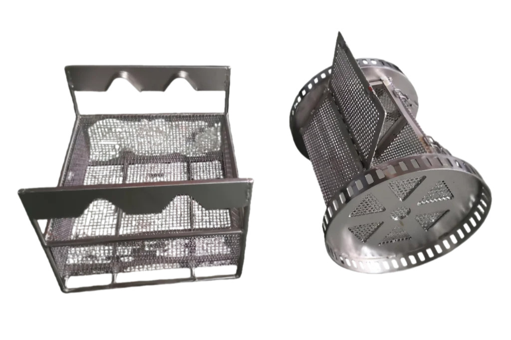
The transfer mechanism also influences cleanliness. Rotary basket systems, which tumble parts through wash and rinse cycles, provide the 360° exposure needed for small, complex components, but that same motion can scratch or gall softer metals. A static fixture with targeted spray nozzles and ultrasonic immersion may be a better fit for a polished optical component. That choice must be made early, because retrofit solutions to correct a basket‑induced scratch problem are rarely satisfactory.
To illustrate how industries differ in practice, the table below summarizes the cleaning priorities that typically drive line design for three high‑precision sectors.
| Industry | Typical Cleanliness Target | Preferred Cleaning Method | Key Equipment Feature |
|---|---|---|---|
| Aerospace hydraulics | ≤ ISO 16232 ‑/19/16 | Multi‑stage aqueous ultrasonic | Vacuum drying for internal passages |
| Medical implants | NVR ≤ 0.1 mg/cm², particle size ≤ 25 µm | Aqueous ultrasonic with DI rinse | Cleanroom‑compatible passthrough |
| Optical components | Surface energy ≥ 60 dynes/cm, no particles > 10 µm | Gentle 80 kHz ultrasonic, ultrapure water rinse | Static fixture, air‑knife drying |
Production validation catches the most common cleanliness inspection failures
Even a well‑designed cleaning line will eventually produce an out‑of‑spec part if validation protocols are weak. The most frequent failures I have encountered in the field come from two root causes: inconsistent extraction procedures during quality checks, and process drift in the rinse tanks.
In the first case, an operator pulls a part from the line and performs a light surface rinse for NVR analysis, never fully extracting residue from a deep internal thread. The lab test shows a pass, but the part is still contaminated. The correction, which we now recommend as part of equipment commissioning, is to standardize the extraction method per the worst‑case cavity in the part family, and to validate that the extraction efficiency is above 90% for that feature.
The second case is trickier because it develops over time. As rinse water picks up detergent carry‑over, conductivity rises, and suddenly the drying step leaves a faint but rejectable residue on the part surface. A conductivity meter with a high‑limit alarm on the final rinse tank is a low‑cost preventative, yet many legacy lines lack it. For solvent systems, solvent purity monitoring through acid acceptance testing or refractive index provides the same protection. Without these inline checks, a cleanliness problem can run for a full shift before a downstream process catches it — and by then, the cost of rework is compounded.
Frequently asked questions about precision manufacturing cleanliness
What is the difference between particle count and non‑volatile residue, and do I need both?
Particle count measures solid debris; NVR measures thin‑film contaminants that are soluble but leave a residue after evaporation. In precision manufacturing, both are typically required because they address different failure modes. A part can pass particle count and still fail coating adhesion if NVR is high due to residual coolant. I recommend running both on qualification lots, then establishing in‑process monitoring thresholds based on the one that correlates most strongly with downstream yield in your specific process.
Is ultrasonic cleaning always required to meet precision cleanliness standards?
Not always. Simple external surfaces with only light oil can be cleaned to high standards with spray washing and DI rinsing. However, as soon as the part has blind holes, threads, or internal intersections, ultrasonic cavitation greatly increases the probability of consistently meeting a sub‑50 µm particle limit. The decision hinges on the part geometry, not the industry alone.
How often should I validate our cleaning process?
Validation frequency is a function of production risk. A high‑volume automotive line running a stable chemistry might validate with a full cleanliness test once per shift plus a daily NVR check. A low‑volume aerospace line processing flight‑critical components will likely validate every batch with both particle count and NVR, at least until enough statistical process control data exist to reduce sampling. If your rinse tank conductivity is continuously monitored, you gain confidence to extend the interval safely. Share your production volume and part criticality with us and we can recommend a validation schedule that fits your resources without compromising quality.
When a precision cleaning line fails to meet its target, the root cause usually sits in one of three places: a standard that was selected without reference to the actual contaminant profile, a measurement protocol that does not extract contamination from the part’s worst cavity, or an equipment configuration that cannot hold fluid purity across production shifts. Solving it rarely requires new chemistry — it requires a process audit that traces the problem back to the design decision where the standard, the part, and the machine diverged. If that exercise points to a piece of missing infrastructure, our engineering team can review your part data and current line configuration to identify the most direct path to compliance — often with a combination of rinse upgrades, drying modifications, and tank re‑sequencing rather than a full system replacement. Reach us at [email protected] or +86 17768507147 with your part number and cleanliness target, and we will confirm the technical feasibility and projected cleaning cycle.
If you're interested, check out these related articles:
Ultrasonic Transducer Technology: An Expert’s Guide to Industrial Cleaning
Ultrasonic Cleaning Energy Costs Minimizing Strategies
Die-Cast Cleaning Solutions for Industrial Parts - GTK
Implement Solvent Recovery Systems: A Factory Efficiency Guide
 English
  German
  Spanish
  French
  Russian
  Portuguese