

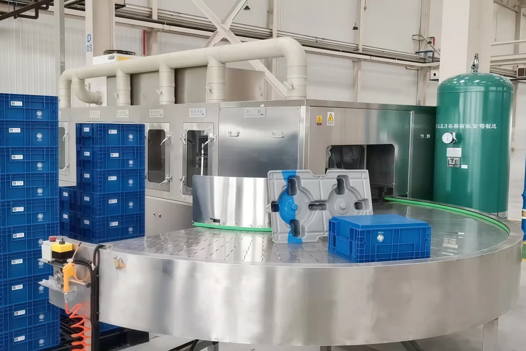
Tunnel cleaning systems achieve consistent, high-throughput industrial parts cleaning, but real-world performance comes down to how the design is matched to specific part geometry, contamination, and throughput targets. In two decades of designing automated cleaning lines for clients in automotive, aerospace, and precision machining, I have repeatedly seen that a standard "off-the-shelf" approach fails when part features like blind holes, recesses, or fragile surfaces are involved. A system that cleans one part perfectly can leave residue on another if the conveyor speed, spray configuration, or chemical delivery was chosen without accounting for those differences. This article covers the critical design parameters and performance trade-offs that engineers, production managers, and procurement teams must evaluate when specifying a tunnel cleaning system. It walks through conveyor and part handling, process design, throughput versus cleanliness balancing, and how customization turns a generic washer into a reliable production asset.
Tunnel Cleaning System Design and Cleaning Performance
A tunnel cleaning system is not a single machine but a continuous, multi-stage line where conveyor, spray, ultrasonic, rinse, and drying sections work as one. The performance of the whole system depends on decisions made at each stage. In my experience, the most common source of under-performance is a mismatch between the cleaning media contact time and the part contamination level. For example, die-cast aluminum shells with release agent require a longer spray dwell time at higher pressure than stamped steel parts with light oil. If the conveyor speed is set to match the faster part, the aluminum parts will exit with residue.
The table below summarizes how key design choices directly affect cleaning outcomes.
| Design Parameter | Performance Impact | Typical Adjustment Range |
|---|---|---|
| Conveyor speed | Determines cycle time and contact duration; faster speed reduces dwell time in spray and ultrasonic zones. | 0.5–1.0 m/min for heavy contamination, up to 2 m/min for light soils |
| Spray nozzle type and pressure | Flat fan nozzles cover large surfaces; conical nozzles reach gaps. Higher pressure (5–10 bar) improves mechanical removal but may cause foaming. | 2–10 bar depending on part geometry |
| Ultrasonic frequency | Lower frequencies (20–28 kHz) produce larger cavitation bubbles for heavy soils; higher frequencies (40–80 kHz) for precision parts. | 20 kHz for stampings, 40 kHz for electronics |
| Number of rinse stages | Each additional stage reduces drag-out and improves final cleanliness, but increases footprint and water use. | 2–3 stages for most applications, 4+ for critical coatings |
I have learned that a 10% increase in conveyor speed can cut cleaning efficacy by more than 25% on parts with deep recesses because the cavitation in the ultrasonic tank does not have enough time to dislodge particles. That is not a linear trade-off, and it explains why setting speed purely by production targets often produces reject parts.
Tunnel Cleaning System Conveyor and Part Handling Design Factors
Conveyor design is the skeleton of a tunnel cleaning system. If it cannot hold the part securely in the right orientation through every stage, no amount of spray pressure or ultrasonic power will save the result. In our cleaning equipment design work, the first question we ask is not "how fast" but "what is the worst-case orientation for contamination retention?" The conveyor must then be built to keep that orientation or rotate the part through multiple positions.
The choice between belt, chain, and roller conveyors depends on part size, weight, and cleaning compatibility.
| Conveyor Type | Best For | Limitations |
|---|---|---|
| Mesh belt | Small to medium parts, high throughput, good drainage | Limited for parts that nest or shift |
| Slat / chain | Heavy or irregular parts, fixtures possible | More complex cleaning access |
| Roller | Parts with flat bottoms, heavy loads | Not for small parts that can jam |
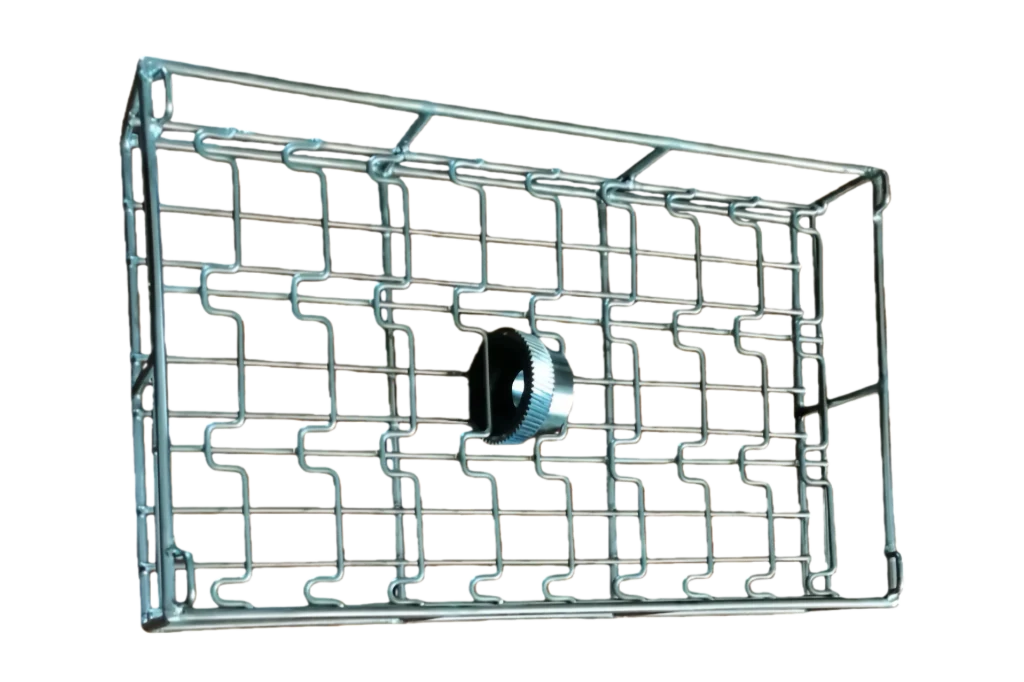
Part fixture design is equally important. A fixture that touches too much of the part surface creates "shadow" areas where spray and ultrasonic waves cannot reach. We design fixtures that contact only non-critical surfaces or use rotating baskets that expose all faces during the cycle. For an automotive bearing washing project, the rotary basket approach achieved a 40% improvement in blind‑hole cleanliness compared to a static fixture.
Spray, Ultrasonic, and Chemical Process Design Parameters
Once the part is moving correctly through the tunnel, the cleaning process itself must be configured for the specific contaminant. Most tunnel systems combine spray pre-wash, ultrasonic immersion, rinse, and drying. The design parameters within each stage determine whether the system meets the cleanliness specification.
For spray zones, nozzle placement and overlap are critical. I prefer a layout with angled nozzles above and below the conveyor, arranged so that every square centimeter of the part sees at least two spray streams. Pressure is typically 3–8 bar, with higher pressure for oil removal and lower for delicate parts. In ultrasonic tanks, the frequency and power density must be matched to the component material and soil type. For machined steel parts with cutting oil, 20 kHz at 10–15 watts per liter works well. For aluminum parts, 40 kHz reduces the risk of surface pitting.
Chemical selection interacts with mechanical action. Alkaline detergents at 50–65 °C are effective for most metal parts; for aluminum, pH must stay below 10 to avoid etching. Rinse water quality is the last link in the chain—if the final rinse uses untreated tap water, mineral deposits will undo the cleaning. We always specify DI water with conductivity ≤ 5 µS/cm for critical applications, such as pre-coating or medical device cleaning.
If your process involves parts with blind holes or deep recesses where spray alone may not fully penetrate, it is worth confirming the right ultrasonic frequency and detergent combination. Contact our team at [email protected] for a process recommendation based on your specific part samples.
Throughput and Cleanliness Trade-Offs in High-Volume Production
Every tunnel cleaning system has a throughput ceiling. The maximum parts per hour is set by the slowest process stage—usually drying or ultrasonic dwell time. When a production manager asks me for "the fastest possible line," I ask what cleanliness specification they must meet. Because beyond a certain speed, cleanliness falls off sharply.
Consider a typical tunnel line for fasteners. A system with a 0.8 m/min conveyor and three ultrasonic degreasing tanks might clean 2 tons per hour of bolts to a heavy-oil-free standard. If the same line is run at 1.2 m/min to meet a spike in production, oil residue may increase by 30–50%. One of our fastener system projects included an oil-water separator and automatic chemical dosing to maintain cleaning consistency even at elevated speeds. That reduced oil carry-over into the rinse tanks and allowed a 15% throughput increase without sacrificing quality.
Balancing throughput and cleanliness demands a clear priority. When the end user requires compliance with ISO 16232 or VDA 19, the cleanliness target must dictate the speed, not the opposite. A realistic approach is to design the system with sufficient tank volume and dwell time for the highest contamination load expected, then use variable speed drives to reduce cycle time when running parts with lighter soils.
Customizing Tunnel Cleaning Systems for Specific Manufacturing Needs
Standard tunnel cleaning systems exist, but standard parts do not. Every factory I have visited that achieved consistently high cleanliness had a system tailored—sometimes slightly, sometimes extensively—to their part families. Customization does not always mean higher cost; it means aligning the design to the production reality.
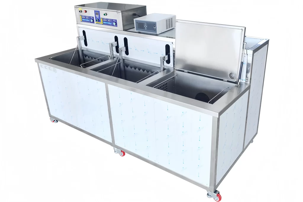
For a plant running multiple part numbers, a tunnel with programmable recipe management on the PLC is worth the investment. The same conveyor can slow down for heavy stampings and speed up for light bolts, while spray pressures and ultrasonic power adjust automatically. At GTKCLEAN, we build systems with Siemens or Mitsubishi PLCs and HMI touchscreen interfaces that store dozens of cleaning programs, allowing quick changeover between part types.
Other useful customizations include modular tank inserts that let a tunnel switch between aqueous and solvent cleaning with minimal downtime, or basket designs that accommodate part families with a common fixture interface. If you are planning a line for a new product launch, it is worth building in extra tank capacity and drying length upfront, because upgrading a tunnel later is far more expensive than adding a stage during initial manufacturing.
Common Questions About Tunnel Cleaning System Design and Performance
What is the typical throughput of a tunnel cleaning system?
Throughput varies widely. A small system cleaning complex castings may process 200–400 parts per hour, while a dedicated fastener tunnel line can handle over 2 tons per hour. The determining factors are conveyor speed, number of process stages, and dwell time required to meet the cleanliness specification. Part handling time also matters—a fully automatic loading/unloading system maintains steady throughput, while manual loading creates variability. For parts requiring long ultrasonic dwell or a multi-stage drying sequence, throughput drops accordingly.
How do I know if my parts need ultrasonic or spray cleaning?
It depends on the contamination type and part geometry. Spray cleaning is effective for loose chips, light oils, and contaminants on accessible surfaces. Ultrasonic cavitation is necessary when the part has blind holes, threads, cross-drilled passages, or tight gaps where spray fluid cannot circulate. Most tunnel systems combine both: an initial spray zone for bulk oil removal, then an ultrasonic immersion tank for precision cleaning. I have found that parts destined for PVD coating or medical assembly almost always require ultrasonic because any residual particle in a recess will cause coating failure.
What maintenance does a tunnel cleaning system require?
Daily checks should cover spray nozzle blockage, conveyor belt tracking, and chemical concentration levels. Weekly tasks include strainer cleaning, filter inspection, and pump seal condition. Monthly, verify heater operation, check ultrasonic transducer bonding, and run PLC diagnostics. The design should include quick-access panels and removable covers to minimize maintenance time. A well-maintained system can operate for years with only routine service; neglect leads to buildup of swarf in tanks and degraded cleaning performance. If you are planning your maintenance budget, ask us for a schedule tailored to your operating hours at [email protected].
If you're interested, check out these related articles:
Choosing the Right Ultrasonic Cleaning System for Industrial Success
Ultrasonic Cleaning System Components Explained
Choosing a Reliable Ultrasonic Equipment Manufacturer: A Strategic Guide
Precision CNC Part Cleaning Solutions - GTK
 English
  German
  Spanish
  French
  Russian
  Portuguese