

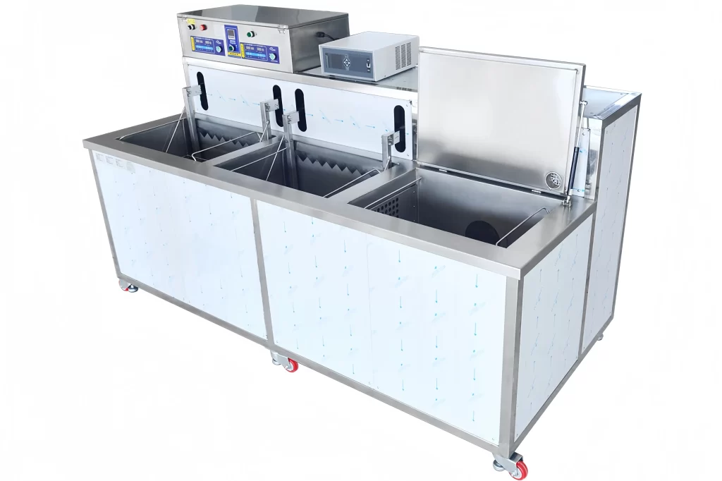
Ultrasonic cleaning has become an essential step in precision manufacturing for removing post-machining contaminants like cutting oils, coolant residues, and metal chips. While the basic principle of cavitation is widely understood, many production engineers still struggle with the specific challenge of eliminating both oil and fine chips from complex part geometries in a single, reliable process. Drawing on twenty years of industrial cleaning system design, this article explains how to configure ultrasonic cleaning to tackle oil and chip removal simultaneously, focusing on tank layout, filtration, process parameters, and production line integration.
Why Machined Parts Demand Thorough Multi-Contaminant Cleaning
Machined components carry a mix of contaminants that affect downstream processes differently. Cutting fluids and lubricants leave an oily film that interferes with coating adhesion and assembly fits. Metal chips ground fines and burrs trapped in threads or blind holes cause mechanical interference or later contamination in precision assemblies. If either contaminant type remains, the part fails quality checks regardless of how well the machining operation was performed. I have inspected parts where a single chip lodged in a critical oil gallery caused a complete engine test rejection months after manufacturing. The cleaning stage must remove both oil and particulate matter to a consistent standard.
What makes simultaneous oil and chip removal different from simple degreasing?
Degreasing alone can dissolve light oils but leaves solid particles behind. Mechanical chip removal methods like high-pressure spray can dislodge chips but may not fully thin out tenacious films. Ultrasonic cavitation addresses both mechanisms simultaneously by creating microscopic vapor bubbles that implode on part surfaces, stripping away oil films while the associated micro-jetting dislodges chips from crevices. The key is configuring the system so that the cleaning fluid remains clean enough to prevent redeposition.
How Ultrasonic Cavitation Tackles Both Oil and Metal Chips
The physics of ultrasonic cavitation is well documented, but its practical effect on mixed contaminants is less commonly discussed. When high-frequency sound waves propagate through a cleaning solution, they create alternating low- and high-pressure cycles. During the low-pressure phase, vacuum bubbles form; during the high-pressure phase, these bubbles collapse violently, generating localized shockwaves and temperatures of several thousand degrees on a microscopic scale. For oil removal, this action emulsifies the hydrocarbon film, breaking it into tiny droplets that are then suspended and flushed away. For solid chips the same implosion forces act like countless micro-hammers, dislodging particles from the metal substrate even inside small-diameter holes and recesses.
The effectiveness on chips depends significantly on frequency selection. Lower frequencies around 20 kHz produce larger, more energetic cavitation bubbles that excel at removing heavier chips and thicker cutting oil residues. For fines and micron-level particles, a moderate 40 kHz or higher yields smaller bubbles that penetrate narrow gaps more effectively. In practice, a system handling mixed part families benefits from a multi-frequency capability or a carefully selected middle ground—typically 28 kHz or 40 kHz for general machining contaminants.
Configuring the Ultrasonic Cleaning System for Mixed Contaminants
A single tank ultrasonic bath alone is rarely sufficient for production cleaning of machined parts. The contaminants lifted from the parts remain in the solution; without proper engineering, they redeposit as drying spots or residual contamination. Our approach, based on installations across automotive and precision machining plants, uses a multi-tank layout with distinct process steps.
The first station is a high-pressure spray pre-wash. This removes the bulk of chips and loose oil before the parts enter the ultrasonic tank, significantly extending the life of the ultrasonic detergent and reducing the load on filtration. The ultrasonic degreasing tank follows, typically operating at 45–65°C with a detergent formulated for cutting oils. After ultrasonic exposure, the parts pass through a rinse section—reverse osmosis or deionized water—to remove any remaining detergent and suspended contaminants. The final stage is drying, either hot air or vacuum drying for parts with complex internal cavities.
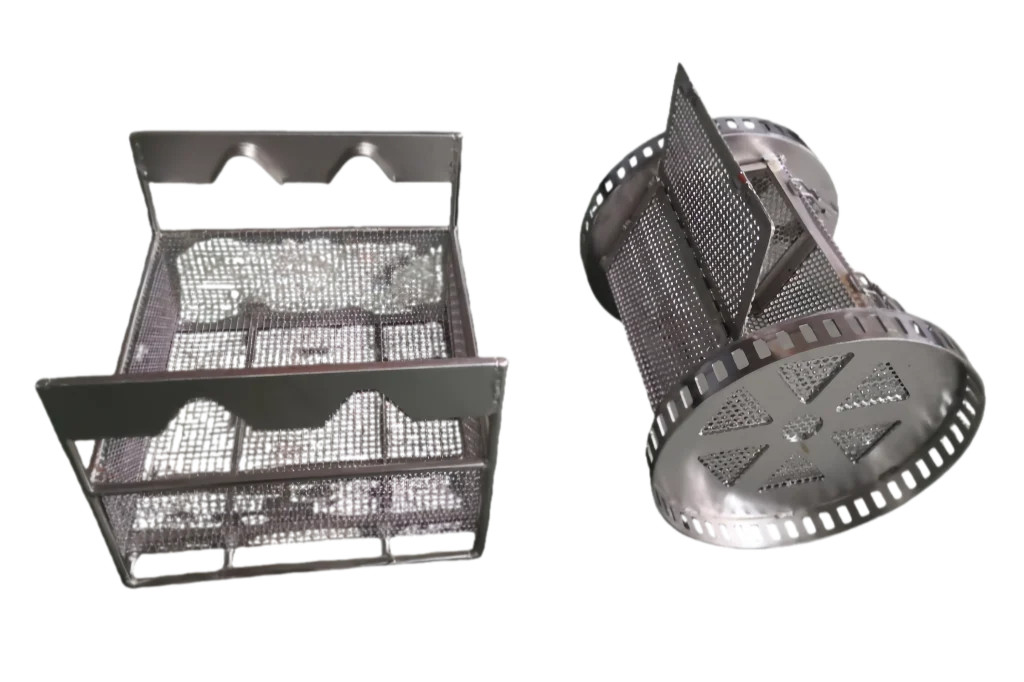
Filtration is the single most important design element for chip removal. Without continuous circulation and filtration, chips accumulate in the tank and eventually settle back on cleaned parts. We install multi-stage filtration: a coarse mesh or bag filter to capture larger chips, followed by finer cartridge filtration down to 10 microns or less depending on the cleanliness specification. The circulation pump should be sized to turn over the tank volume at least three to four times per hour, ensuring that suspended particles are constantly removed from the process. Additionally, an oil skimmer or coalescer removes floating oil to prevent it from redepositing during the rinse or dry stages.
Basket design directly impacts chip removal. For parts with blind holes, a stationary basket may trap chips that the cavitation detached but gravity cannot pull out. We often specify rotary baskets that turn the parts during cleaning, allowing chips to fall free. For heavy or plate-type components, a square basket with dedicated part fixturing prevents part-to-part contact and ensures all surfaces face the transducer array. The basket material must be stainless steel 304 or 316 for chemical resistance and sufficient open area to allow unrestricted cavitation energy transmission.
If your parts feature deep internal cavities or geometries where chips become trapped, a standard configuration may leave residues that later appear as field failures. Our team has resolved such issues with customized rotary basket systems. For an evaluation of your part geometry, reach us at [email protected].
Process Parameters That Improve Oil and Chip Removal
The interplay of temperature, detergent, cycle time, and ultrasonic power determines whether the system meets the required cleanliness specification. The table below summarizes typical parameters for machining contaminants.
| Parameter | Recommendation | Effect on Oil and Chip Removal |
|---|---|---|
| Frequency | 20–40 kHz | Lower for large chips, higher for fine particles and film removal |
| Temperature | 45–65°C | Reduces oil viscosity and improves detergent action; too high degrades ultrasonic transmission in some solutions |
| Detergent type | Alkaline or neutral pH, specific for cutting fluids | Emulsifies oil and prevents re-deposition; avoid high-foam detergents that dampen cavitation |
| Cycle time | 5–15 minutes per tank | Longer times improve chip removal from complex geometries but must be validated against production throughput |
| Ultrasonic power density | 10–30 watts per liter | Higher power achieves faster cleaning; excessive power can cause surface erosion on soft metals |
I have observed that when the cleaning solution is not properly matched to the machining coolant chemistry, detergent effectiveness drops sharply and oil residues remain. This is particularly problematic with water-soluble coolants that create stubborn films. A simple jar test with the coolant and detergent can predict compatibility, saving significant debugging time during commissioning.
Integrating Ultrasonic Cleaning into the Machining Production Line
For high-volume production, the cleaning system must fit within the manufacturing takt time without compromising cleanliness. This often means moving from a batch manual ultrasonic cleaner to an automated multi-tank or inline conveyor system. The machine loading interface matters: parts can be fed directly from the machining center into the cleaning line via robotic transfer or a simple basket loading station. For mixed part numbers, recipe-based PLC control (Siemens or Mitsubishi) with touchscreen HMI enables operators to switch programs quickly, adjusting cycle times, temperatures, and ultrasonic power per part type.
Drying is the final critical step. Water spots or residual moisture inside threaded holes cause corrosion. For most machined steel and aluminum parts, an air knife combined with hot air circulation is sufficient. For blind holes and deep recesses, we use vacuum drying that lowers the boiling point of water, pulling vapor out of confined spaces. Water treatment for the rinse section, including RO or DI water with conductivity monitoring, prevents mineral spots on parts destined for coating or assembly.
The system should also include process monitoring: conveyor speed, tank temperatures, ultrasonic power output, and conductivity of rinse water. This data supports process validation for quality systems like ISO 9001 or IATF 16949. Where clients require documented cleanliness levels, we integrate inline particle counters or simple visual inspection stations before the drying stage.
Common Questions About Machined Parts Cleaning
Can ultrasonic cleaning remove heavy grease and thick, embedded chips?
It can, but it works best as part of a multi-step sequence. Heavy grease often requires a pre-wash with a high-alkaline detergent or solvent to break down the heavy layer before ultrasonic cavitation finishes the film removal. For thick chips, a pre-spray with pressurized fluid removes bulk material so the ultrasonic tank can focus on the finer particles lodged in crevices. In our installations, we have seen cycle times reduce by 30% when a targeted pre-wash precedes ultrasonic cleaning.
How do you prevent chips from redepositing on cleaned parts?
Through a combination of continuous filtration, proper tank overflow design, and basket rotation. The filtration loop must capture particles before they settle. Overflow weirs remove floating contaminants, and the basket rotation ensures gravity assists chip removal during the ultrasonic phase. Additionally, we design the transfer between tanks so parts are not exposed to a contaminated rinse solution.
Is ultrasonic cleaning safe for delicate machined surfaces like aluminum alloys or precision-bearing fits?
Yes, with appropriate frequency and power density control. At 40 kHz and moderate power, cavitation is gentle enough for aluminum and even polished surfaces. However, soft metals are susceptible to cavitation erosion at high power and low frequencies over long cycles. I recommend starting at 40 kHz and validating surface finish before committing to a lower frequency. Parts with pressed-in components require testing to ensure the ultrasonic energy does not loosen assemblies.
What maintenance does an ultrasonic cleaning system need?
Daily checks include verifying ultrasonic generator output, inspecting filtration cartridges, and skimming oil from tanks. Weekly chemical titration ensures detergent concentration remains within the specified range. Monthly, transducer plates or immersion boxes need visual inspection for corrosion or delamination. Rinsing water quality must be monitored continuously via conductivity meter; if it exceeds 10 µS/cm, the resin or membrane should be replaced. A well-maintained system typically runs for over 10 years with periodic tank degreasing and pump overhauls. If your production relies on documented cleanliness, we can provide ongoing maintenance support and process qualification documentation—share your requirements with us at [email protected].
Achieving consistent removal of both oil and chips from machined parts is a systems-engineering problem, not just a detergent choice. A correctly configured ultrasonic cleaning line with multi-stage tanks, continuous filtration, and matched process parameters delivers reliable cleanliness for even complex geometries. If you are specifying a new cleaning system or troubleshooting an underperforming one, send your part prints and production volume to [email protected] or call +86 17768507147. We will help you define a cleaning process that matches your throughput and cleanliness targets.
If you're interested, check out these related articles:
What Is The Piezoelectric Effect?
Industrial Ultrasonic Cleaners Versus Traditional Cleaning Methods
Die-Cast Cleaning Solutions for Industrial Parts - GTK
The Engineer’s Guide to Pre-Coating Surface Preparation
 English
  German
  Spanish
  French
  Russian
  Portuguese