

Precision components with blind holes, internal threads, and complex geometries present a cleaning challenge that standard immersion ultrasonic systems often fail to solve. A static basket leaves some surfaces shielded from cavitation for the entire cycle, producing inconsistent results that downstream processes like coating, assembly, or inspection will expose. Rotary ultrasonic cleaning systems address this by continuously repositioning parts through the ultrasonic field, but their real-world effectiveness depends on design decisions made long before the first cycle runs. After two decades of specifying and deploying these systems across industries from automotive to medical device manufacturing, I have found that the gap between acceptable and exceptional cleaning results narrows to three factors: basket design, rotation parameter matching, and process validation.
How Rotary Motion Changes Ultrasonic Cleaning Performance
In a static ultrasonic tank, cavitation bubble formation and collapse concentrate along the transducer-facing surfaces. Whatever part geometry faces away from that energy remains in a relative dead zone. For a flat washer or simple plate, this matters little. For a precision-machined housing with intersecting cross-drilled holes, it means coolant residue stays put in the cavities that never face the transducer array.
Rotation changes the energy distribution pattern by continuously exposing every external surface and internal cavity to the high-intensity cavitation zone. More practically, it creates a mechanical flow effect inside blind holes. As the part rotates through the cleaning medium, the liquid inside cavities experiences pressure differentials that pulse fresh solution into and spent solution out of confined spaces. I have measured cleanliness improvement of over 40% on cross-drilled hydraulic components simply by moving from static to rotary fixturing with the same ultrasonic power input.
The interaction between rotation speed and ultrasonic frequency also matters. At 20 kHz, cavitation bubbles are larger and more energetic. Fast rotation at this frequency can create uneven cleaning if the part moves through the cavitation field faster than bubbles can fully form and collapse on surface contaminants. At 40 kHz or 80 kHz, where cavitation is finer and more uniformly distributed, higher rotation speeds work beneficially to ensure all surfaces receive equal exposure. For most precision work below 100 mm in diameter, we default to 28–40 kHz with rotation between 3 and 8 rpm, adjusting based on the smallest internal feature that needs cleaning.
Basket Design Considerations for Precision Components
The basket is not a container. It is a process control device. Its design determines which surfaces see cavitation, how parts are protected during cleaning, and whether the system can be automated.
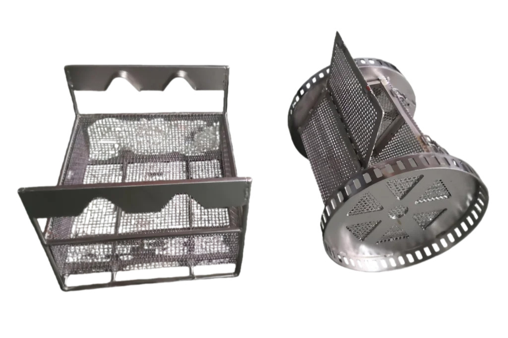
Rotary ultrasonic systems use either round baskets for complex three-dimensional parts or square baskets for flat, plate-type components. Round baskets rotate continuously, tumbling parts gently to expose all surfaces. Square baskets can rotate incrementally or in indexed positions, which matters when parts have one critical surface that must not contact anything. For collision-sensitive components like finished bearing races or polished optical housing surfaces, individual fixturing within the basket is non-negotiable.
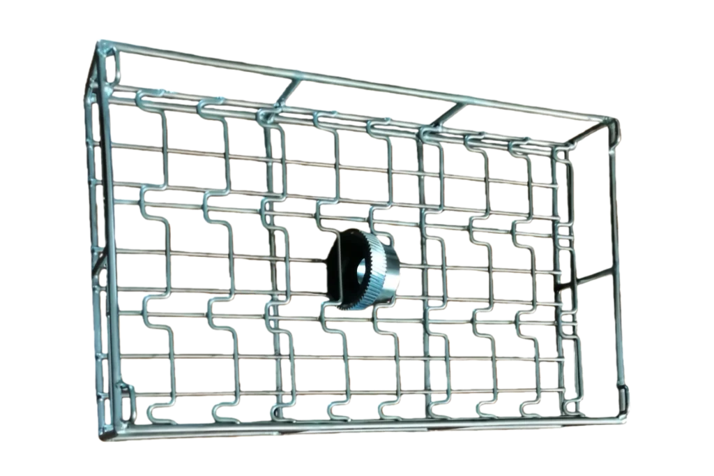
The basket material decision carries more weight than it seems. Stainless steel 304 baskets are standard, but for precision aluminum components, even 304 can leave micro-scratches if parts tumble freely. In those cases, we specify SUS316 with electropolished surfaces, or PTFE-coated contact points for the most delicate parts. At GTKCLEAN, we have built rotary systems handling loads up to 2,000 kg with reinforced basket structures, motors, and tank frames engineered specifically for those loads. But load capacity is only one number. The ratio of basket open area to total surface area determines how much ultrasonic energy actually reaches the parts. Too much metal and the basket absorbs energy meant for cleaning. Too open and heavy parts distort the basket over time. For precision work, I typically design baskets with 60 to 70 percent open area, using wire diameters of 3 to 5 mm for most industrial loads.
Part fixturing inside the basket is where many systems fall short. A precision fuel system component with a 0.2 mm orifice requires a different holding strategy than a transmission gear being degreased before assembly. If your program involves parts with feature sizes below 0.5 mm, it is worth confirming that the basket design includes positive fixturing rather than relying on part-on-part contact during rotation. Send your part drawings and throughput targets to [email protected] and we can confirm the fixturing configuration that matches your geometry.
| Basket Type | Best For | Rotation Mode | Typical Load |
|---|---|---|---|
| Round, full-immersion | Complex 3D parts, blind holes | Continuous 360° | Up to 500 kg |
| Square, indexed | Flat parts, single critical surface | Indexed positions | Up to 800 kg |
| Reinforced heavy-duty | Large castings, engine blocks | Continuous or indexed | Up to 2000 kg |
| Custom-fixtured | Precision components <0.5mm features | Application-specific | Varies |
Matching System Configuration to Part Requirements
A rotary ultrasonic system is not one machine. It is a sequence of stations, and the configuration of those stations determines what cleanliness level is achievable and at what throughput.
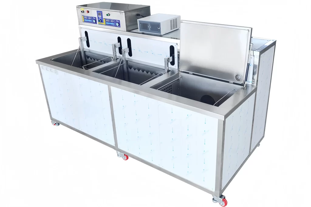
For precision components requiring pre-coating cleanliness, a three-stage or four-stage rotary system is standard: ultrasonic degreasing, followed by one or two RO or DI water rinses, then hot air or vacuum drying. The degreasing stage uses either water-based detergent at 45–65°C or hydrocarbon solvent at 40–60°C, depending on the contaminant and part material. For parts destined for PVD or DLC coating, the rinse water must meet ultrapure standards, with conductivity at or below 0.06 μS/cm. Water spots are not cosmetic on coated parts. They are bond-line defects.
Frequency selection is the parameter where I see the most mismatches in specification. A system purchased for cleaning both brass instrument valves and hardened steel injection nozzles needs different frequencies for each, but many buyers fixate on power ratings instead. For precision components with fine surface finishes under Ra 0.4 μm, 40 kHz or higher prevents cavitation erosion while still achieving adequate cleaning. For parts with heavy machining oils or heat treatment scale, 20–28 kHz provides the energy needed, though it requires careful cycle time control to avoid surface pitting on softer materials.
Tank sizing is another underexamined variable. The cleaning tank must accommodate the basket plus sufficient freeboard for ultrasonic field development. A tank that barely fits the basket creates standing wave patterns and inconsistent cleaning. I specify tank dimensions with at least 100 mm clearance on all sides of the basket and 150 mm below for transducer array placement. For a rotary system, the tank diameter also must account for the full rotational sweep of the longest part in the basket, not just the basket diameter at rest.
The drying stage choice depends on part geometry more than on preference. Hot air drying works for simple external surfaces. Parts with blind holes, threaded cavities, or capillary channels retain liquid that hot air cannot remove, leading to water spots or solvent residue. Vacuum drying pulls liquid out of these confined spaces by reducing the boiling point. For precision hydraulic components, I have seen vacuum drying reduce post-cleaning particle counts by over 60 percent compared to hot air alone, simply because it eliminated liquid entrapment.
Process Validation and Quality Control for Precision Cleaning
A system that cleans well but cannot prove it cleans well will fail at audit. Process validation for precision components requires defining what "clean" means for your specific parts, then measuring against that definition consistently.
Surface cleanliness after rotary ultrasonic cleaning is typically verified by one of three methods depending on the industry and risk threshold. For general industrial parts, a water break test or dyne ink test confirms that oils and films are removed by checking surface wettability. Automotive and aerospace specifications more commonly require gravimetric analysis, where residual contamination is washed off a cleaned part, filtered, and weighed. For medical devices and optical components, particle counting with ISO 4406 or equivalent standards provides the resolution needed to detect contamination below visible levels.
I learned early in my career that validating only external surfaces is a mistake. A precision component that passes a visual inspection with flying colors can still carry machining chips inside a blind threaded hole that will destroy a mating assembly. For rotary systems, validation must include cross-sectioning sample parts or using borescope inspection of internal features on a defined sampling frequency. The rotation mechanism solves the cleaning challenge for internal features, but the validation protocol must confirm it.
Common failure modes in rotary ultrasonic cleaning for precision parts include residue redeposition when the rinse stage is undersized or overloaded, surface pitting from excessive cavitation energy at low frequencies on soft alloys, and water spotting when DI water resistivity drifts above specification. Each of these has a specific process control solution, not a generic one. Redeposition means either more rinse stages or lower drag-out between tanks. Pitting means frequency adjustment or reduced cycle time. Water spotting means inline resistivity monitoring with automatic DI water regeneration.
Integrating Rotary Systems into Automated Production Lines
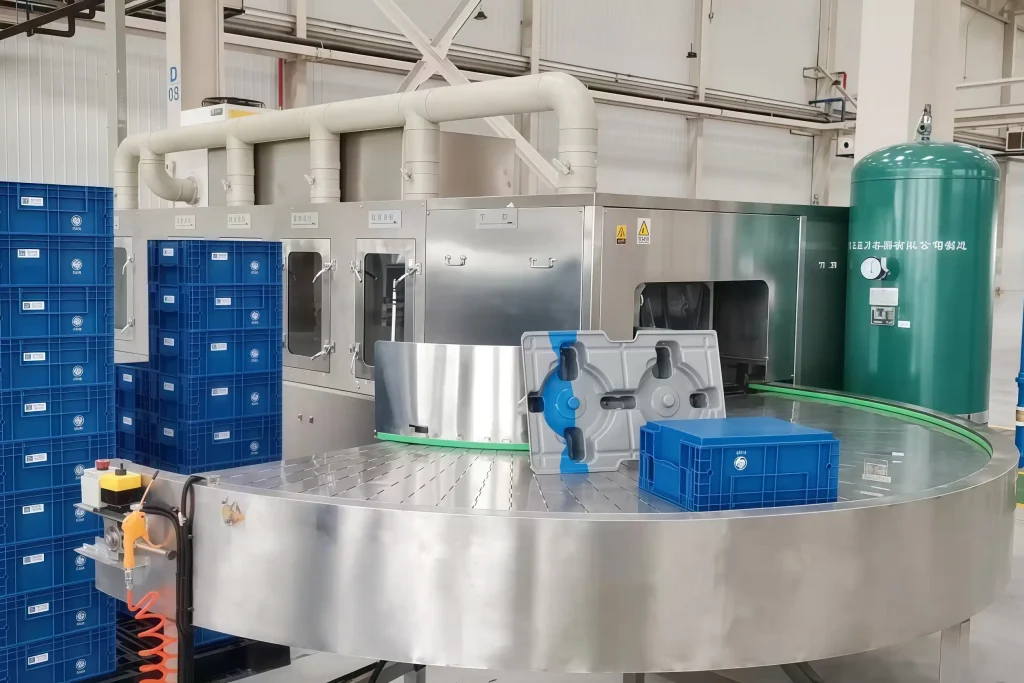
Rotary ultrasonic systems integrate into automated production lines at two levels. The first is basic conveyor interfacing, where parts arrive in baskets or on trays and a pick-and-place or gantry system loads them into the rotary cleaning basket. The second is full recipe-based automation, where part-specific cleaning programs call up the correct cycle parameters automatically.
For high-mix precision manufacturing environments making small batches of different components, recipe-based automation eliminates operator error. A Siemens or Mitsubishi PLC with touchscreen HMI stores cleaning, rinsing, and drying parameters for each part number. When the operator scans a barcode or selects a program, the system sets the correct temperature, ultrasonic power, rotation speed, and cycle time without manual adjustment. At GTKCLEAN, we have deployed these systems where process programs can be remotely upgraded, reducing the need for on-site service calls across the 20-plus countries we support.
The load and unload interface requires as much engineering attention as the cleaning itself. A rotary system that cleans perfectly but requires manual loading and unloading creates a bottleneck that defeats the throughput gain. If your program is moving toward lights-out operation or continuous production flow, confirm that the basket handling mechanism is compatible with your existing conveyor or robotic automation standards before finalizing system specifications.
Achieving Consistent Results with Rotary Ultrasonic Cleaning
Precision cleaning fails at the margins. It fails in the blind hole that was drilled one millimeter deeper than the validation test part. It fails on the alloy variant that is softer than the standard grade. It fails when the rinse water quality drifts slowly enough that nobody notices until coating rejects spike three weeks later.
Rotary ultrasonic cleaning systems close the gap between average and complete cleaning by eliminating the static dead zones that leave internal features contaminated. But closing that gap requires the right basket for the part, the right frequency for the material, the right rinse configuration for the cleanliness target, and a validation protocol that proves what the eye cannot see. After two decades of designing these systems for manufacturers across automotive, aerospace, medical device, and electronics industries, my recommendation is to evaluate the system as a complete process, not a piece of equipment. The cleaning result is only as strong as the weakest stage in the sequence.
If you are specifying a rotary ultrasonic system for precision components or upgrading an existing line, send your part drawings, material specifications, and cleanliness requirements to [email protected] or call +86 17768507147. We will confirm the basket design, tank configuration, and process parameters that match your parts and your throughput targets.
Common Questions About Rotary Ultrasonic Cleaning for Precision Parts
How do I determine whether my parts need a rotary system or a standard ultrasonic cleaner?
It depends on your part geometry and the location of the contamination you need to remove. If your parts are flat plates, simple bushings, or components where every surface is visible from the outside, a standard ultrasonic system with proper fixturing may suffice. The rotary system earns its cost when you have blind holes deeper than 1.5 times their diameter, intersecting internal passages, threaded cavities, or recessed features that trap machining fluid. In programs we have supported, I recommend running a static test cycle first. If you can section a sample part afterward and find residue in any internal feature, the rotary investment is justified.
What basket material should I specify for precision aluminum components?
For aluminum precision parts where surface finish matters, do not use standard 304 stainless steel baskets if parts will tumble freely. The hardness difference means the basket will micro-scratch aluminum surfaces. Specify electropolished SUS316 or use PTFE-coated contact surfaces on the basket. For the most delicate components like polished optical housings, individual fixturing with polymer contact points eliminates part-to-part and part-to-basket contact entirely. This adds cost to the basket but prevents scrap that far exceeds the basket investment on the first production run.
Can rotary ultrasonic systems handle parts with internal threads smaller than M3?
Yes, but it requires frequency selection and cycle time tuning. At 40 kHz, cavitation bubbles are small enough to penetrate and collapse inside M2 and M3 threaded holes, removing cutting oil and fine chips. At 20 kHz, the larger bubbles may not fully enter small threads. The rotation mechanism helps by pulsing cleaning solution through the threaded cavity, but the combination of higher frequency and rotation produces the most consistent result. For threads below M2, add a dedicated high-pressure spray stage before ultrasonic cleaning to dislodge bulk contamination from the thread roots.
How often should I validate cleaning results on a rotary system in production?
For precision components in regulated industries, validate at every shift start with a standard test part that represents your worst-case geometry. For automotive tier-one production, daily validation with gravimetric or particle-count methods is typical, with full process capability studies quarterly. The rotation mechanism adds a wear component that static systems do not have. Basket bearings, motor seals, and rotary unions all have finite life, and their degradation can affect cleaning uniformity before a failure alarm triggers. Include these components in your preventive maintenance schedule and validate cleaning performance after any rotary drive component replacement.
What is the most common mistake when specifying a rotary ultrasonic cleaning system for precision work?
Under-specifying the rinse stage relative to the cleaning stage, and skipping process validation on internal features. I have seen systems where the ultrasonic degreasing tank was generously sized and correctly powered, but the rinse tank was half the volume with no circulation filtration. The result was consistent oil redeposition as drag-out from the cleaning stage overwhelmed the rinse water within the first hour of production. Size the rinse stage to at least match the cleaning stage volume, add overflow and filtration, and monitor rinse water resistivity or contamination level continuously rather than on a time-based schedule. Share your requirements and we will confirm the rinse stage configuration needed for your target cleanliness level.
If you're interested, check out these related articles:
Upgrading to Automated Ultrasonic Cleaning Systems for Efficiency
Industrial Ultrasonic Cleaning Systems: Diverse Applications Guide
How to Ensure Perfect Coating Adhesion Without Water Spots or Stains?
How to Choose Multi-Tank Ultrasonic Systems for High Volume
Why Coating Manufacturers Choose GTKCLEAN Pre-Coating Cleaning Equipment
 English
  German
  Spanish
  French
  Russian
  Portuguese